
Torque Converter Tech Tips
- Author: Ed Lee
When learning to scuba-dive or skydive, you are specifically taught to make one only change at a time. In those situations, complicating your routine may be life threatening.
In industry, change is necessary to keep up with your competition. Making changes means moving forward, while not making changes can actually be the same as moving backward. Change may be good, but be careful; what may appear to be a change to only one step in a process may actually be changing more than one thing at a time.
In the following situations each converter builder made what he believed to be a single change. For each of them, the change did not seem to cause any problems at first. Unfortunately, devastating long-term consequences occurred in both situations because they failed to realize that they had made more than one change.
In the first situation, a torque-converter rebuilder started getting returns on his 298mm and 300mm converters. The returned converters had TCC codes and appeared to have friction-material de-bonding issues. The rebuilder had been bonding his 298mm and 300mm pistons the same way for many years with great success.
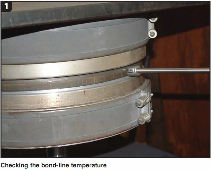
He had recently started bonding with a new friction material, and all the failures seemed to be limited to converters with the new material. He reviewed his setup procedure with the new material and found only one small difference. The piston was getting to the correct bond-line temperature a few minutes sooner than with the friction material he had been using previously (Figure 1). He believed this was a plus and did not look into it any further.
This rebuilder made one major mistake during his setup procedure; he failed to recognize one difference caused by the change in friction material. For the past several years he had been bonding with a tan or Kevlar® friction material. The new friction material was spun woven. His bond-line temperatures and clamping pressures were fine, but he failed to recognize how much faster the spun-woven material would transfer heat. He had skipped the step of doing a temperature curve on the new material. When he went back and defined the temperature curve on the spun-woven material, he found that the adhesive passed through the flow zone in about 18 to 19 seconds.
According to the Torque Converter Tech Tips article in the June 2008 issue of Transmission Digest, the flow zone occurs when the bonding adhesive is in its liquid state, and the flow zone needs to be between 45 and 90 seconds long for a good bond. To get the flow zone to an acceptable time, the rebuilder added a 0.070-inch-thick friction ring as an insulator between the piston and bottom bonder plate but found that his bond-line temperature was now too low. A small increase in temperature on the bottom bonder plate brought the flow zone and temperature into the proper parameters.
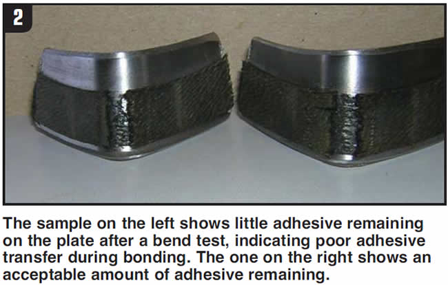
Besides not plotting the temperature curve, the rebuilder also did not do a bend test on the new friction material. A later failed bend test did show that there was very little transfer of adhesive from the friction material to the piston (Figure 2). Doing the temperature curve or the bend test would have identified a potential problem and might have prevented the costly comebacks.
The second situation was much like the first. The second rebuilder also started seeing returned units with de-bonding issues, and the person doing the bonding had not changed his bonding setup. The person doing the bonding had a successful history of bonding the double-sided TCC piston for the 3060 World Class Allison converters and the double-sided piston in the B 500 converters used in buses. Since his bonding process had not changed in years, the bonder could not understand why he was starting to have problems.
The rebuilder had recently requested that the Kevlar friction material be changed from 0.040 inch to 0.070 inch thick. The returned units all had the new 0.070-inch-thick friction material. When the bonding process was rechecked, it was discovered that the time in the flow zone was too long and the bond-line temperature was about 100°F shy of the desired level.
The incorrect assumption that the existing bonding setup could be used with the thicker material, since the makeup of the material had not changed, was a very costly mistake. The temperature at the bonder plates was increased, in an attempt to reach the desired bond-line temperature, but the increased heat glazed the surface of the friction material before the temperature was achieved. Returning to the 0.040-inch friction material was the only way that the bond-line temperature could be maintained without damaging the material.
The lessons here are:
- Never assume that your bonding setup will work after you make a change, no matter how small or routine the change seems to be.
- DO NOT short-cut the setup process! (This includes doing temperature curves and bend tests.)

Ed Lee is a Sonnax Technical Specialist who writes on issues of interest to torque converter rebuilders. Sonnax supports the Torque Converter Rebuilders Association. Learn more about the group at www.tcraonline.com.


