Technically Speaking
- Subject: Operation and diagnosis of Hall-effect speed sensors
- Units: AF23/33-5 (AW55-50SN), 5R110W
- Essential Reading: Rebuilder, Diagnostician
- Author: Wayne Colonna, ATSG, Transmission Digest Technical Editor
Several years ago (back in 2005) I wrote an article called “Getting Up to Speed” for the Technically Speaking column. It was a simple presentation showing the pros and cons concerning the three different types of speed sensors used in automatic transmissions: pulse generators (AC sensors), a reed switch (on/off pulse signal using mechanical parts) and Hall-effect sensors (a glorified reed switch not using mechanical parts).
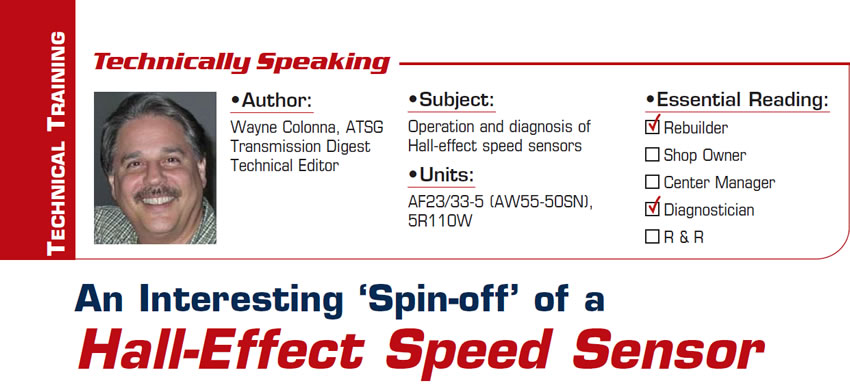
Since the time of writing that article, it seems the Hall-effect style of sensor is favored among the manufacturers, most likely because of its reliability and the cost effectiveness of producing it. This sensor can be either a two- or three-wire design, with the frequency signal being generated by a magnetic wheel (ring) or by the teeth of a gear. The three-wire design consists of a voltage-supply wire, a ground and a signal wire. The two-wire design has a voltage-supply wire and a signal wire. For this two-wire sensor to work a resistor inside the TCM/PCM is wired to ground, allowing the voltage on the signal wire to drop when the rotating magnet is used to “chop” the sensor circuit and producing the signal pulse.
By the very nature of a Hall-effect sensor’s design, the signal wire is never fully pulled down to 0 volts. The signal wire in a two-wire Hall-effect sensor will usually have a pulse from 0.5 to 1.5 volts (Figure 1).
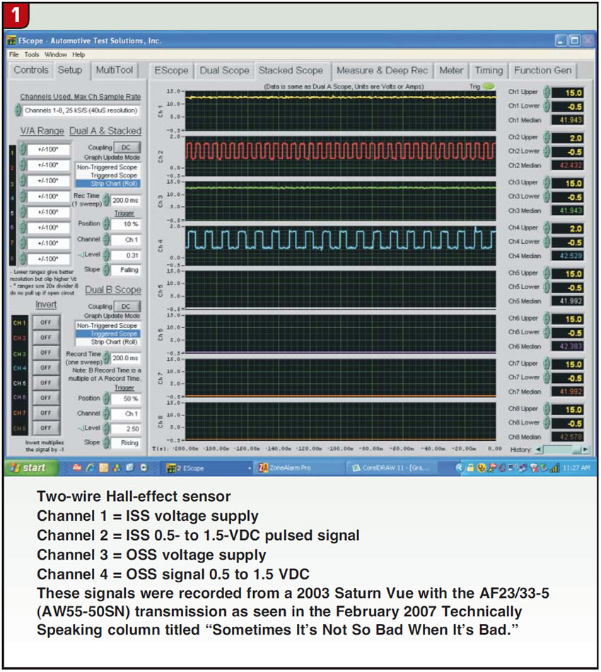
A three-wire sensor will typically have about a 0.5- to 5-volt pulse (Figure 2).
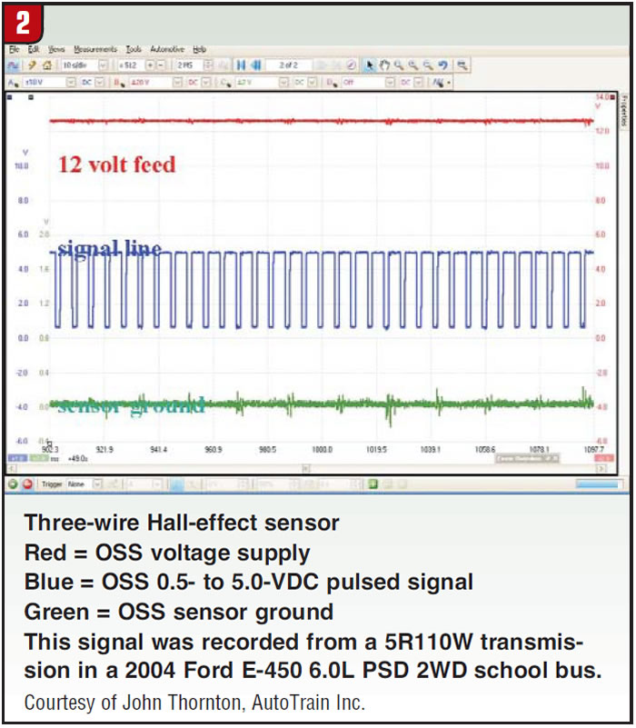
However, there is an interesting “spin-off” (no pun intended) in diagnosing a Hall-effect sensor, and that is when the signal line gets shorted to ground (Figure 3).
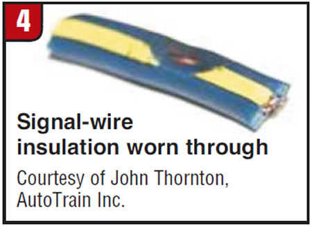
Since the design of the Hall-effect sensor is to pull the signal line down to 0.5 volt, a short to ground pulling it to a full 0 volt (if there is any such thing as a full 0) becomes quickly identifiable. The wire had rubbed against metal, which wore through the insulation, resulting in an intermittent short to ground (Figure 4).
If a sensor is designed to produce a pulsed on/off signal where the signal wire is supposed to be pulled down to 0 volt, when it becomes intermittently shorted to ground it will not be as easily detected as it is with a Hall-effect sensor. One would have to look at the time base in the signal to determine that it’s being shorted to ground.
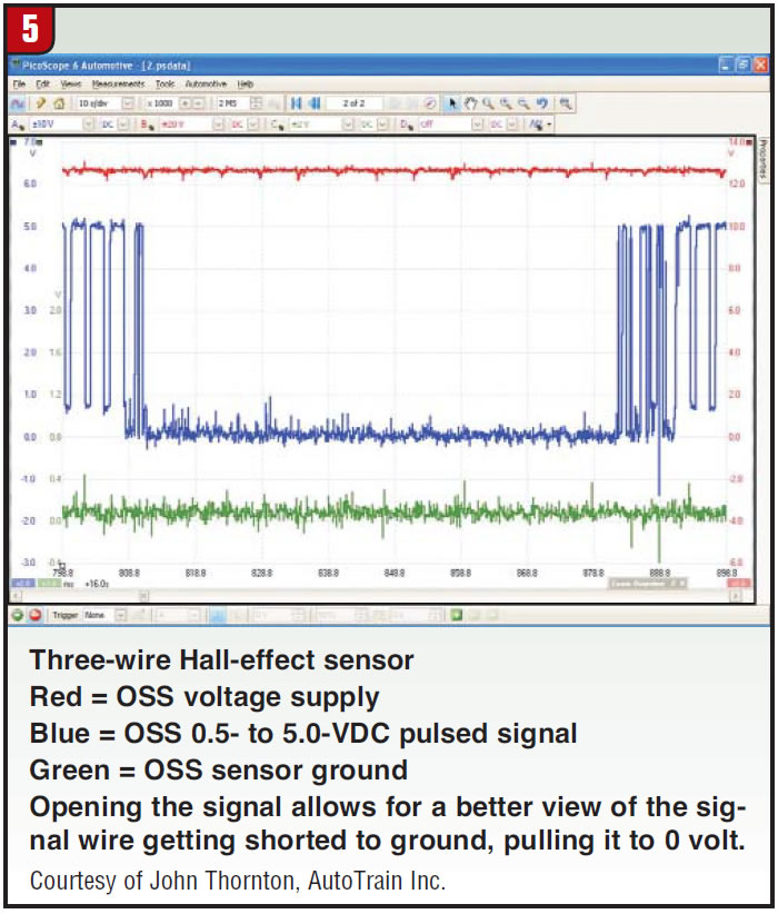
By opening the captured three-wire Hall-effect sensor’s signal wire to have a better look at its being intermittently shorted to ground (Figure 5), you can easily see how it went from being pulled down to 0.5 volt to 0 volt and back again to 0.5 volt. But notice how long it was being held to 0 volt as opposed to when it was being held to 0.5 volt. This is how you would be able to determine a short to ground with a signal that is supposed to be pulled to 0. Compare the time base from a normal pulse with a short to ground; the time base will be notably different.


