Technically Speaking
- Author: Wayne Colonna, Technical Editor
Identifying the different styles of speed sensors can be tricky
There are basically three different styles of speed sensors a transmission diagnostician has to deal with: a reed switch, an AC generator (pulse generator) and a Hall-effect sensor.
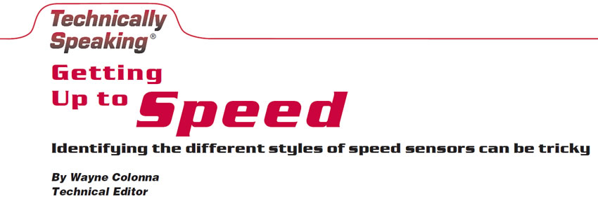
The reed switch is usually in the speedometer head of the instrument cluster. As a cable drives the speedometer head, a wheel with magnets or cams that pull or push contacts together grounds a 5-, 8- or 12-volt wire from the computer. This produces a pulse voltage of 0-5-0-5, 0-8-0-8 or 0-12-0-12-0-12 that the computer can interpret as a square-wave vehicle-speed signal. The usual failure of this sensor is that the spring-loaded contacts that push apart weaken and at higher speeds the contacts do not pop away as quickly, causing an erratic square-wave signal at higher speeds (see Figure 1). This, of course, translates into no high gear, and shift and/or TCC shuttle.
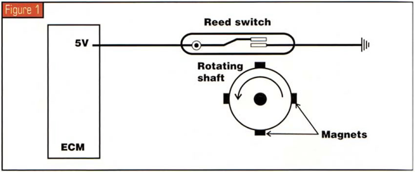
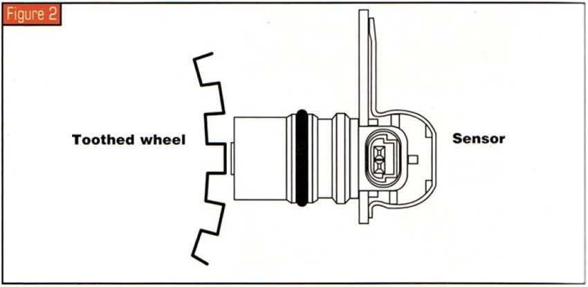
AC generators are constructed with wiring wrapped around a magnet producing a magnetic field (in most transmission applications). As a toothed wheel passes by the tip of it, each tooth disrupts the magnetic field. This magnetic field induces an alternating-current (AC) voltage into the coil windings. The AC voltage pulses have a frequency in proportion to the speed of the rotating part.
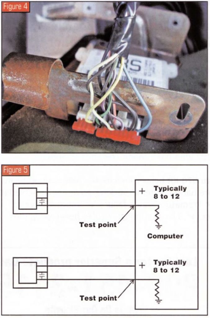
The computer needs to have this signal converted into a square-wave signal similar to that of the reed switch (see figures 2 and 3). This is why we saw digital ratio adapter controllers (DRACs) or speed buffers on GM vehicles, for example (see Figure 4). This AC signal was conditioned inside the DRAC box, and a five-volt wire from the computer then was pulsed to ground at the DRAC. The computer then read a square-wave signal of 0-5-0-5 DC volts. This style of sensor is subject to radio-frequency (RF) interference, which would cause erratic signals resulting in erratic-shift and TCC complaints.
Another problem is that as the sensor weakens because of heat and/or age, the strength (amplitude) of the AC signal weakens, causing a complaint of no upshift to high gear or falling out of gear.
Then we have Hall-effect sensors, which in the past have been the familiar three-wire speed sensor. This sensor is designed with a voltage supply on one wire, a ground on the second and the signal on the third. This sensor provides a square-wave signal directly into the computer without the assistance of a DRAC.
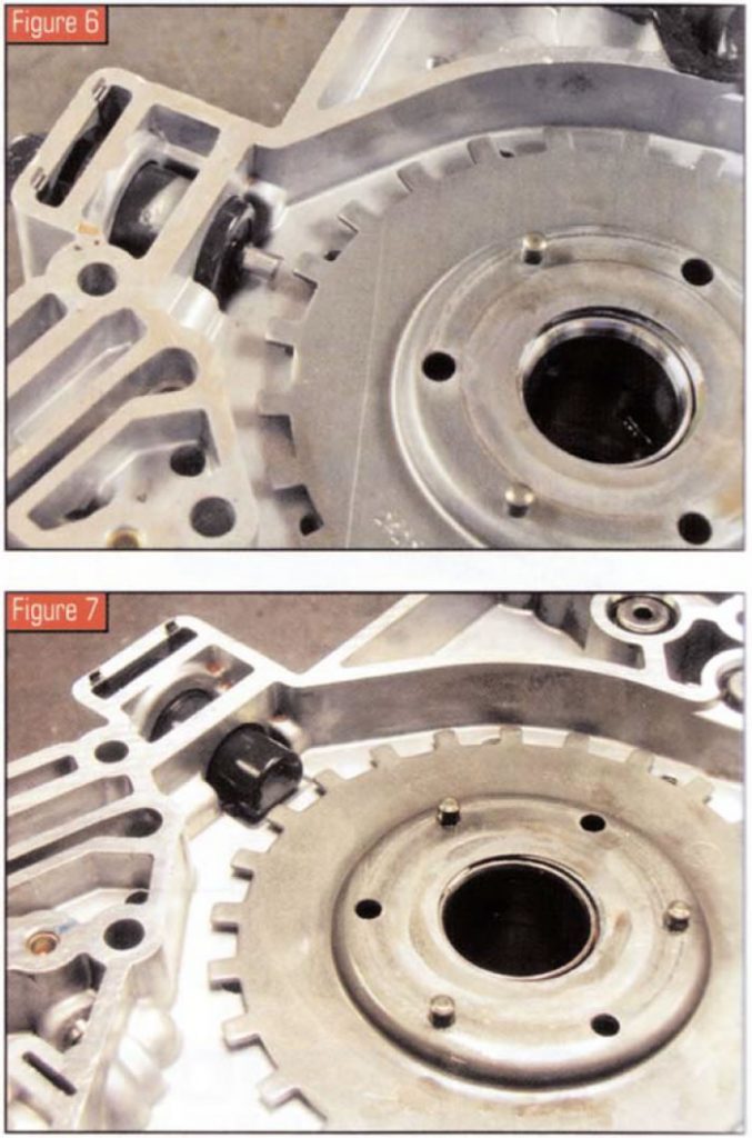
But over the past few years these three-wire Hall-effect sensors have been redesigned to be two-wire sensors and are being confused with AC pulse generators. Simply explained, these new Hall-effect sensors still have three wires, but the third wire is inside the sensor, where a capacitor separates the power supply from the signal (see Figure 5).
The vehicles we have encountered that looked like an AC pulse generator but were two-wire Hall-effect sensors have been the input-shaft speed sensors in Volvo’s 4T65-E and Audi’s 5-HP-19. And if you replace the sensor with an incorrect sensor, you will go insane trying to fix it. You will think there is a wiring nightmare or a computer problem, and it will cost you time and money that you cannot be compensated for.
What makes this somewhat elusive is that there are no positive visible means to distinguish a two-wire Hall-effect sensor from an AC pulse generator. You could say that if there is a magnetic pole sticking off the tip you would know it is an AC pulse generator, and you would be right (see Figure 6). But if you say that a two-wire Hall-effect sensor is one that does not have a magnetic pole sticking out of the tip, like the one in Figure 7, you can be wrong. How about the CD4E sensor in the pump – isn’t the magnetic pole enclosed in a plastic casing? That is an AC pulse generator and would not work as a Hall-effect sensor.
Another thought would be that with AC pulse generators you do not have power supplied to the sensor, but with a two-wire Hall-effect sensor one wire should have battery voltage on it. So if you unplug the sensor, one of the wires should be hot. OK, for the most part that may work, but one day you may have a loss of power to a Hall-effect sensor and you would think, “No voltage? Must be an AC generator system.” Beeeep – wrong again.
Maybe a resistance check would be the way to go, you may say. Well, we are getting closer, but this is not a sure method, either. Usually, if the sensors are good you will get a resistance reading with an AC pulse generator, but with a Hall-effect sensor you will not. I am sure you can see why this is not the best method. If you have a bad AC pulse generator not giving you any resistance, you may incorrectly think you have a Hall-effect sensor.
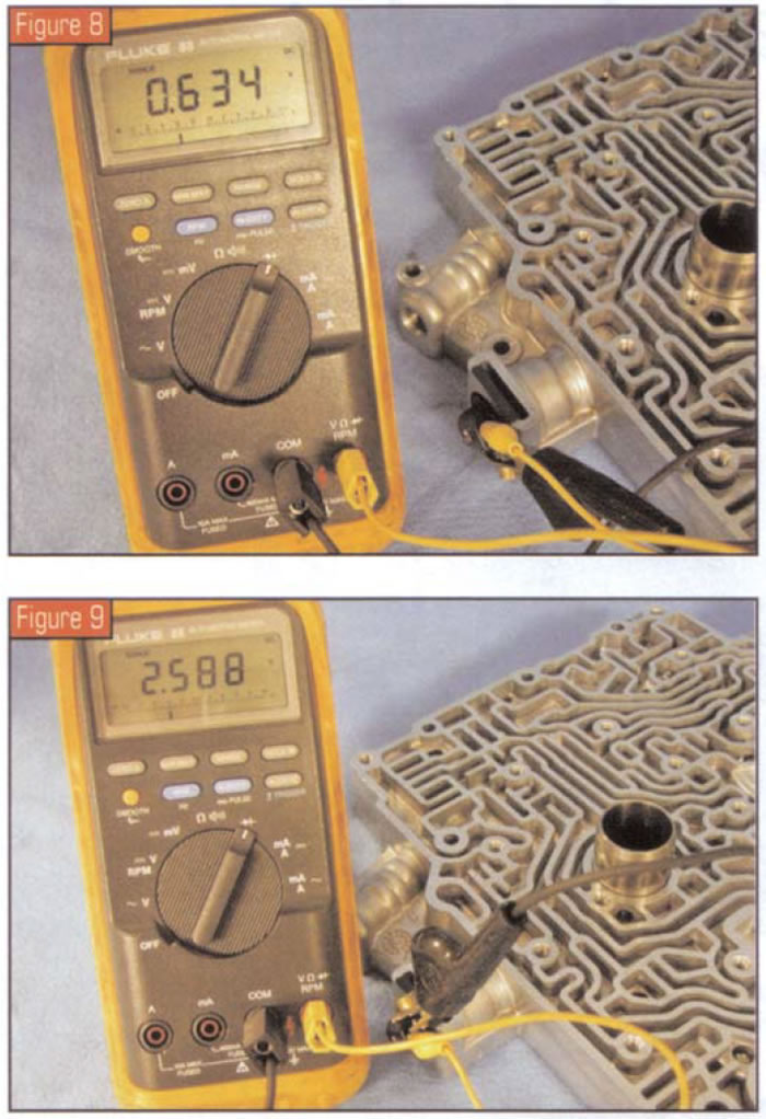
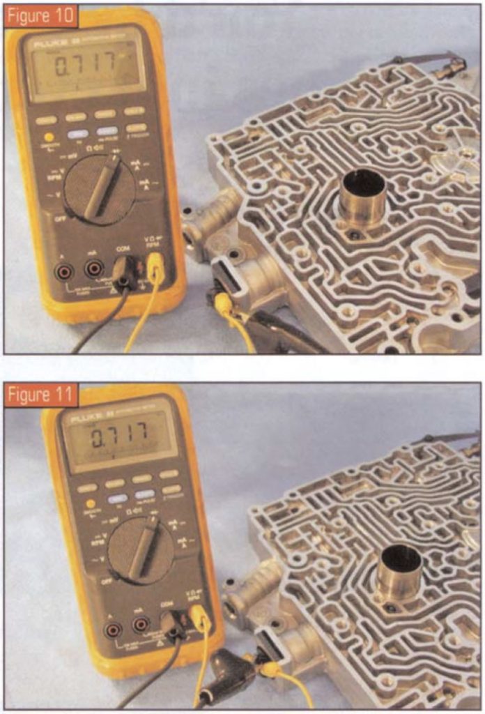
Another way, and perhaps the best method of all (and that is not to say it is a 100% method), is to do a diode test with a digital volt/ohm meter (DVOM). A Hall-effect sensor will give two distinct voltage differences when you switch terminals (see figures 8 and 9), whereas an AC pulse generator will read very little voltage difference and the reading remains the same when you switch leads (see figures 10 and 11). The reason for this is that a two-wire Hall-effect sensor has a diode but an AC pulse generator does not. But, if the diode goes bad in a two-wire Hall-effect sensor, guess what – you may think it’s an AC pulse generator. What a dilemma. You could get fooled any way you try to test.
You could try to check the signal with a scope, which is another preferred method. An AC pulse generator would give you a sine-wave form, and a Hall-effect sensor would give you a square wave. But if the wires are severed or shorted to power or ground, you could be fooled again. What a dilemma!
The absolute best way to distinguish a two-wire Hall-effect sensor from an AC generator is simply to know which type of sensor each vehicle uses. Some to watch for it are all 4T65-Es in Volvo vehicles (both the input and output sensors); the Volvo AW 55-50N, which is the AF23/33-5 in Saturn Vue and Ion (also input and output sensors); and the input sensor on 5-HP-19 in Audi and BMW vehicles.
The most-common incorrect-usage error that takes place is with the Volvo 4T65-E (see figures 6 and 7). As you can see, they are similar in appearance and the connectors are the same.
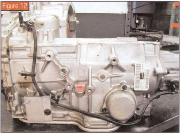
One reason why the input sensor in the Audi 5-HP-19 and the output sensor in the Volvo 4T65-E (see Figure 12) are not mistakenly exchanged is that they both have long pigtail leads as part of the sensor, whereas the pulse generator does not. You would have to go out of your way to get this wrong.
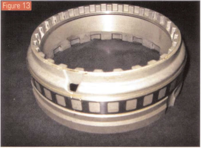
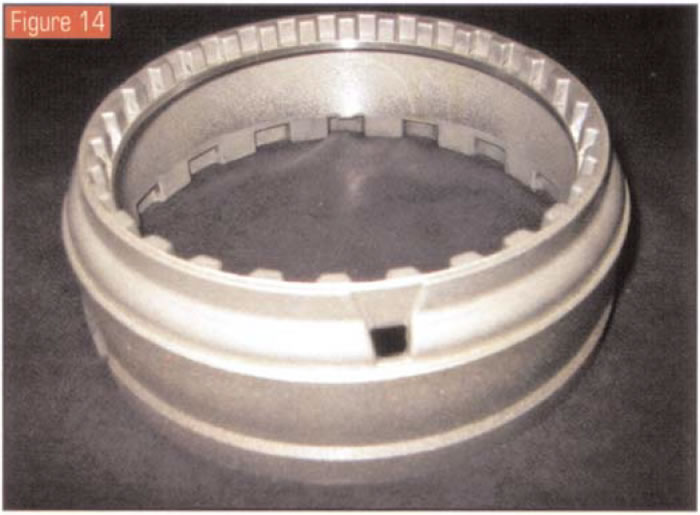
One additional note: There are three basic versions of the 5-HP-19 – rear-wheel-drive, front-wheel-drive and all-wheel-drive. All rear-wheel-drive versions at this time use Hall-effect sensors, but not all the front- and all-wheel-drive versions do; they could have a pulse generator instead. For all the 5-HP-19s that use the Hall-effect sensor, the sensor is excited by a magnetic black ring on cylinder A. But for the front- and all-wheel-drive versions that use a pulse generator, the sensor is excited by a spider-clutch bell that has sheet-metal windows pressed onto it (see Figure 13). The same shell in Hall-effect applications eliminates these sheet-metal windows, as they are not needed (see Figure 14). If you use a spider-clutch bell without the windows in an Audi/VW unit that uses a pulse generator instead of a Hall-effect sensor, it is obvious you will not have a working sensor.
Many thanks to ZF Industries for its assistance.


