Technically Speaking
- Author: Mike Riley, Technical Editor
- Subject Matter: Automatic Transmission
- Unit: 09G/TF-60
- Vehicle Application: Volkswagen
- Issue: Electronic shift controls
The Aisin Warner 09G six-speed FWD transmission, or TF-60, has increased in popularity, and technicians need to become more familiar with all aspects. The 09G can be found in a variety of Volkswagen FWD vehicle platforms produced after 2003. Its close cousins, the TF80 (Volvo and GM) and TF81 (Ford and Mazda), further enhance a huge market potential for the transmission-repair industry.
There has been much focus over the years on valve-body wear issues and other deficiencies of the 09G as well as the TF80/TF81 models. Once a repair had been made, shift or apply issues still existed at times, requiring more attention to the controls.
The experts at Rostra Precision Controls have devoted a substantial amount of effort to determine how all the aspects of Aisin six-speed transmissions (valve body, solenoids and TCM) work together to provide a well-functioning and durable transmission repair.
The following is a summary of that research:
Aisin Warner has made several improvements related to the operation and design of this six-speed family relative to the earlier five-speed (AW55-50) family, including the use of dedicated linear solenoids to directly control clutches. With this improved system, the TCM has more ability to adapt and precisely control the quality of shifts, but ultimately the control is limited. Whenever any conditions change within the hydraulic circuit, such as the valve body or solenoids, adjustments to the system may be necessary. This article will dissect exactly what is happening during select shifts and how to make adjustments to the valve body to obtain the desired level of drivability. The 09G will be the specific focus of the article although most of the information also holds true for the 09D (TR60), TF80 and TF81.
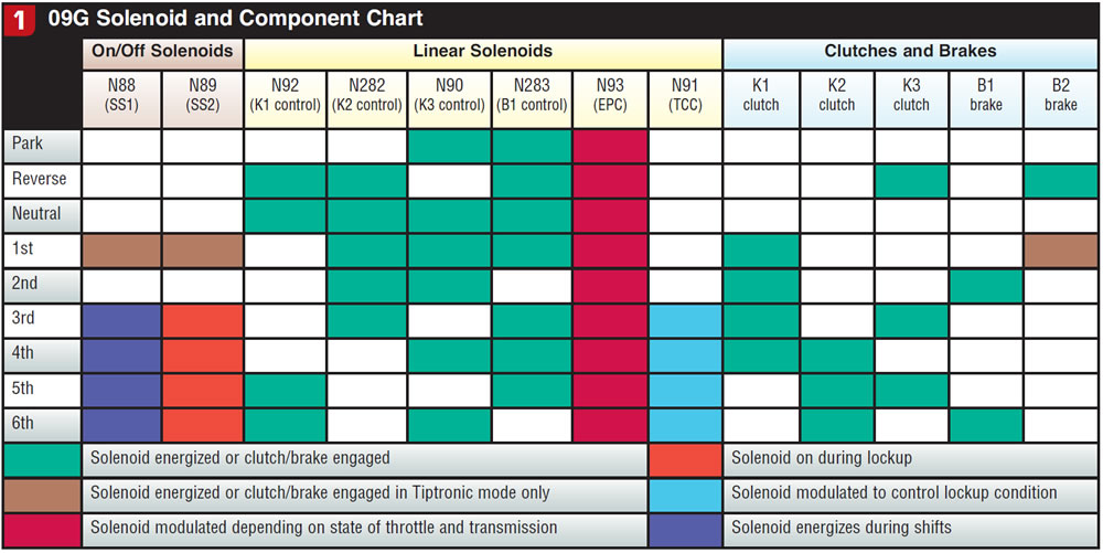
First, let’s examine the solenoids and their roles in the transmission. The 09G has six linear solenoids and two on/off solenoids. Of the six linear solenoids, four of the units directly control clutches and brakes via spring-loaded spool valves in the valve body. The remaining two control line pressure and torque-converter lockup. Five of the linear solenoids are normally open and function to reduce pressure output with increased current draw. The TCC solenoid is normally closed and increases pressure output with increased current draw. The two on/off solenoids are normally closed and are energized for various purposes including engine braking and torque-converter lockup. Figure 1 illustrates the detailed function of each solenoid and clutch.
Operation of solenoids during shifts
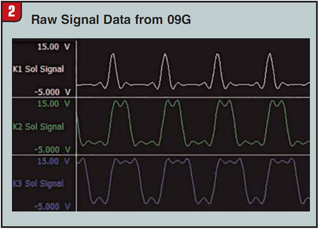
To understand how the linear solenoids control the engagement of the clutches and brakes, we must first understand the signal driving them. The linear solenoids are supplied 12-volt power in the form of a 300-Hz PWM signal. An accepted but ineffective aftermarket industry standard is to simply measure current being supplied to the solenoids to determine load. Because of the variations in current draw depending on heat and specific resistance of the solenoid, measuring duty-cycle percentage is a more-consistent, accurate and preferred representation of solenoid load. The solenoids are driven by signals that vary from 12%-60% duty cycle with 60% being “fully energized,” limiting the normally open solenoid’s output to near 0 psi. At 12% duty cycle the solenoid is essentially off, which allows all input pressure to pass through a normally open solenoid. The majority of pressure modulation occurs between 20% and 55% duty cycle. Figure 2 shows the signals applied to K1, K2 and K3 control solenoids on the tail end of a 3-4 shift, where the duty cycles are 12%, 40% and 60% respectively. As a reference, the time elapsed between each peak is 3.33 milliseconds.
Electronic control over the entire pressure range of the transmission means that the TCM can ramp the rise and drop of pressure to specific clutches and brakes to achieve a smooth shift. Most shifts are comprised of one clutch (or brake) being applied and another clutch (or brake) being released (synchronous shift). In an ideal shift situation, the two components will have minimal time between application of the two components. Figure 3 illustrates how the signals and pressures are being modulated in the same 3-4 shift as featured in figure 2.
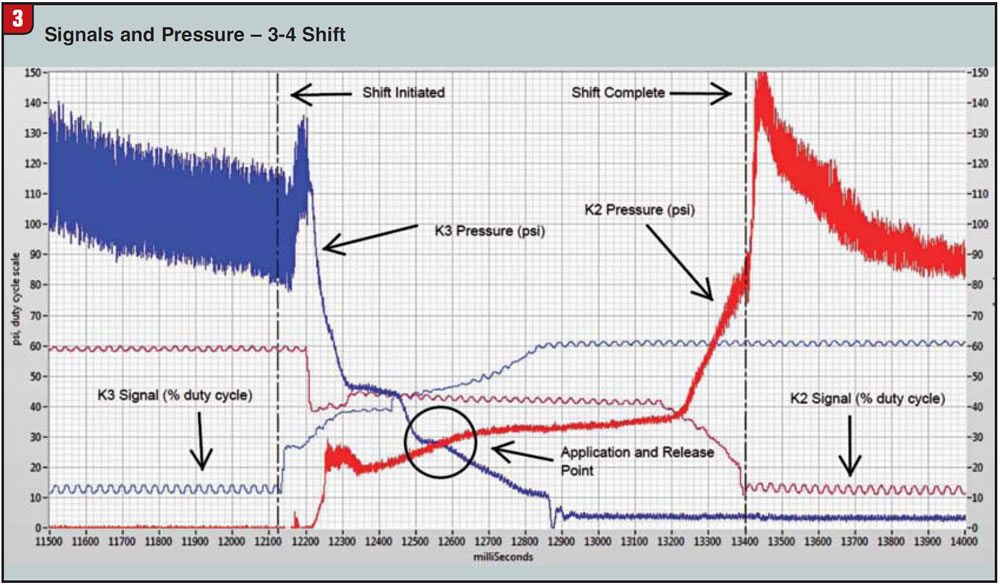
Figure 3 shows that during the 3-4 upshift the K2 clutch is applying and the K3 clutch is releasing. Notice how K3 control solenoid ramps up the signal to inversely drop the pressure in the K3 circuit while, at the same time, the opposite occurs for the K2 solenoid signal and hydraulic circuit. Application pressures for the K2 and K3 clutches are near 30 psi, indicating that for about 100 ms, neither the K2 nor K3 clutch was engaged. If the time between clutch applications was longer (more than one-quarter second) the rpm would begin to rise as if in neutral then drop quickly, resulting in a shift flare followed by a bump. On the other hand, if the K2 clutch is applied before K3 releases, the transmission is effectively trying to operate temporarily in two different gears simultaneously, resulting in a bind-up.

Relearn and calibration
Unlike the solenoids in the AW55 transmission, the AW 6 solenoids are not adjustable. Aisin Warner has elected to compensate for the variations in solenoid output by implementing adjustment screws directly on the valve body. Calibration of the valve body with solenoids installed as a whole system is necessary to ensure a consistent quality of shifts. In the event that any clutch’s control-system output relative to drive signal changes, shift quality and drivability may suffer, resulting in flares or bind-ups. Poor shift performance could be caused by simply replacing solenoids with different preset calibrations or repairing the valve body to fix leaks that the TCM has already taken into account. In most situations the TCM is capable of adjusting the drive signals to smooth out any harsh shifts. Through normal driving, this may be a slow and tedious process requiring up to 50 miles of drive time. To help accelerate this process, it is recommended that the shop perform a relearn procedure.
With the transmission at normal operating temperature and no codes present, shift from Park to Reverse to Neutral to Drive and back, staying in each range for 10 seconds. Repeat this at least five times. Accelerate through the first five gears under light throttle (10%), then come to a stop; repeat five times. Accelerate through all gears at medium throttle (50%), then come to a stop; repeat five times. Manually downshift through all gears; repeat five times. It’s important to remember that the intent of the relearn procedure is to simulate many miles of average driving in a short time. If there is one particular shift that is harsh, it would be beneficial to repeat that shift with greater frequency.
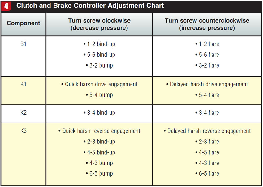
After this relearn procedure has been performed, it is still possible for the hydraulics to be so far from the system’s norm that manual calibration of the valve body is necessary to achieve the desired drivability. The first step in calibrating a valve body is to identify which clutch or brake control needs to be adjusted. Figure 4 illustrates common drivability issues and the appropriate clutch and brake control to adjust to resolve the issue. For example, if a vehicle was experiencing a flare on the 3-4 shift, the resolution would be to turn the adjustment screw on the spring tensioner for the spool valve that shares the bore with the K2 control solenoid counter clockwise. One complete turn of the screw can resolve a slight application issue; two complete rotations of the screw may resolve an obvious flare or bind-up.
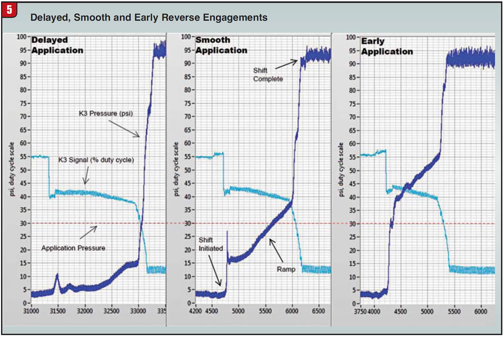
In diagnosing the engagements into Drive and Reverse, determining whether the pressure is too high or low can be particularly tricky. Figure 5 shows the effects of both and high and low K3 pressures on the engagement of reverse. In an ideal clutch application, the pressure gradually rises to 30 psi as seen in the Smooth Application. If the pressure rise is too sudden, the engagement will be harsh. Notice how the early engagement reaches the engagement pressure before the ramp sequence while the delayed engagement finishes the ramp sequence before it reaches the engagement pressure. The harshness of both the early and delayed engagements illustrated in Figure 5 could be perceived to be of the same magnitude. When diagnosing the difference between high and low pressures, it is important to focus on the time between moving the gear selector and the bump that follows. The early engagement will happen almost instantaneously, whereas with the delayed engagement it will take up to two seconds to feel the bump.
The line-pressure circuit and EPC solenoid do not have adjustment screws, and all their corrections are relegated to the TCM. The TCC solenoid does have an adjustment screw that is typically staked and nonadjustable. Similarly, only the TCM can make TCC corrections. Note that if the output pressure is lower than normal in the TCC solenoid, the initial torque-converter lockup engagement in third gear could be firm and feel similar to a 3-4 shift. When diagnosing it is important to confirm which gear is engaged by using a scan tool or the Tiptronic system of the vehicle. Shift firmness should work itself out through the relearn procedure.
The improved design of the hydraulic control system in the 09G allows you to take the guesswork out of resolving drivability issues. Direct control of the clutch and brake components through dedicated solenoids, along with the ability to adjust pressures of the hydraulic circuits, makes diagnosis and resolution of drivability issues more of a science and less of an art.
Currently, OEM solenoids are available only by purchasing an entire valve body. Rostra Precision Controls, however, has linear solenoids available, and with an improved design. Problems with OE solenoids involve wear or debris buildup affecting the internal bushings. Rostra has redesigned the bushings to prevent those issues such as wear or sticking of the spool valve. The solenoid body also has been redesigned for better oil flow. The on-off solenoids are under development as well. Contact Rostra or a Rostra distributor for a complete listing of Aisin solenoids and other Rostra products.
Special thanks to Matthew Charter, product engineer for Rostra Precision Controls, for providing the research and content of this article.