TASC Force Tips
- Subject: Cross leaks between forward- and direct-clutch circuits
- Unit: 4R70W/4R75E, 2001 & later
- Essential Reading: Rebuilder, Diagnostician
- Author: Gregg Nader
When transmission parts fail or have problems, I often think about the decisions made along the way that resulted in the problematic part being used in production. A common sight at many transmission benches these days is a “cracked” separator plate found in 2001 and newer 4R70W/4R75E units. There is more to this story than just the cracked plates discovered during the rebuild, and it started long ago when the decision was made to eliminate a valve-body stiffener plate. I would love to have been a fly on the wall back then, listening to the reasons why it was OK to eliminate the stiffener plate.
Through the 2000 model year, these units had a two-bolt stiffener plate under the 2-3 accumulator. The purpose of the plate was to clamp the separator plate and lower valve-body gasket against the valve-body casting. Beginning with 2001 models, the two-bolt stiffener plate was eliminated. The 2-3 accumulator retainer now sits directly on the separator plate. Another change in this area was that the capacity modulator valve and plug were eliminated from the valve body and the valve bore was cast closed. The unused casting pocket is also directly under the 2-3 accumulator.
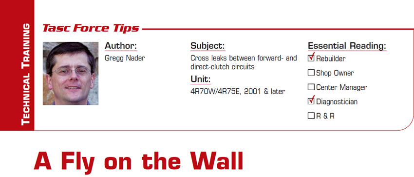
At first glance, you might assume that the cracks we see in the separator plate (Figure 1) are caused by the 2-3 accumulator retainer’s rounded end smacking against the plate. You might also assume the cracks are a problem, but the cracks and the accumulator retainer seating directly on the separator plate are not the problem. The cracks are a symptom of a completely different and bigger problem related to the forward- and direct-clutch circuits.
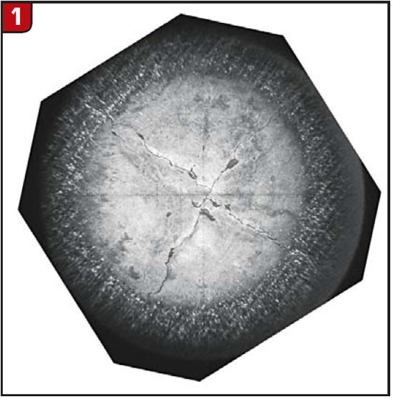
In these units, the forward clutch is fed through the pump at the front of the unit and the direct clutch is fed through the output shaft at the rear. Forward- and direct-clutch oil circuits are separate and, for the most part, kept isolated from each other except for one area. That area is in the casting under the separator plate, below the 2-3 accumulator (Figure 2).
In the 2001-up units, there is no mechanical clamping of the separator plate and valve-body gasket to maintain the seal between the forward and direct circuits. To confirm this on the next one you tear down, look at the imprint the valve-body passages leave on the gasket. Lay the upper gasket over the lower gasket and look closely in the area of the 2-3 accumulator (the smaller of the three openings in the upper gasket). What you will see is a heavy imprint of the valve-body castings across most of the lower gasket except in the area of the 2-3 accumulator. I cannot think of any other transmission where the separator plate/valve-body gaskets have such a large gasket area that is not mechanically compressed.
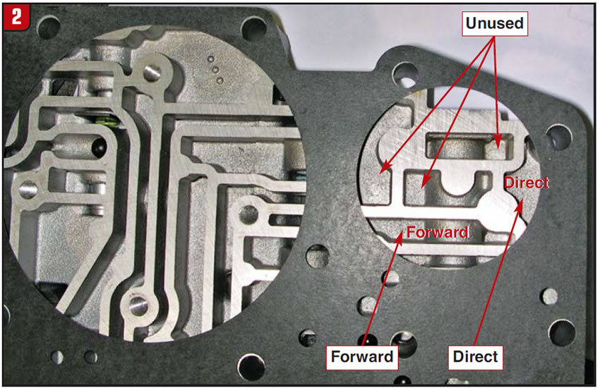
The biggest problem caused by eliminating the two-bolt plate is not cracked separator plates; rather, it is cross leaks between the forward- and direct-clutch circuits. Without mechanical clamping of the gasket, pressurized oil seeps into the unused valve-body passages and pushes upward on the separator plate, similar to how oil pushes on a servo. Figure 3 shows the unit when the forward clutch is applied and the direct clutch is not applied.
When the plate bows upward, the forward-clutch oil pressure bleeds over or cross leaks into the direct-clutch circuit. I have measured the plate bowing upward as much as 0.011 inch with normal (forward) oil pressure.
Cracks in the plate may not look good, but dragging clutches are far more destructive. The problem is not with the separator plate. The problem is that the two-bolt retainer was eliminated.
The only absolute fix to prevent cross leaks between the forward- and direct-clutch circuits is to mechanically clamp the separator plate and gasket to the valve body with a two-bolt plate, as in the earlier models. The bolt-hole locations need to be drilled and tapped, and the separator-plate bolt holes need to be drilled. The lower gasket can be used to locate the holes. If you have earlier valve-body cores lying around, it is easy enough to take the two-bolt plate and modify it to install on the late application; otherwise, look to the aftermarket for a replacement two-bolt retainer plate you can retrofit to later units.
This brings me back to thinking about why they removed the stiffener plate in the first place. With the plan to remove the capacity modulator valve, most (but unfortunately not all) of the valve-body passages under the plate were no longer going to be used. If the circuits were not to be used, eliminating the “unnecessary” plate may have seemed like a good way to save a few pennies per transmission. At some meeting long ago, this must have been discussed and they decided to eliminate the stiffener plate. Penny pinching aside, I would love to know why this seemed like a good idea. I have never seen any other spot in any transmission where you have two oils circuits next to each other in the valve body and no mechanical clamping of the gasket that separates the two.

Special thanks to Rick Nylund for bringing this issue to our attention.
Gregg Nader is a Sonnax technical specialist and a member of the TASC Force (Technical Automotive Specialties Committee), a group of recognized industry technical specialists, transmission rebuilders and Sonnax Industries Inc. technicians.
©2010 Sonnax Industries


