
Technically Speaking
- Author: Wayne Colonna, Technical Editor
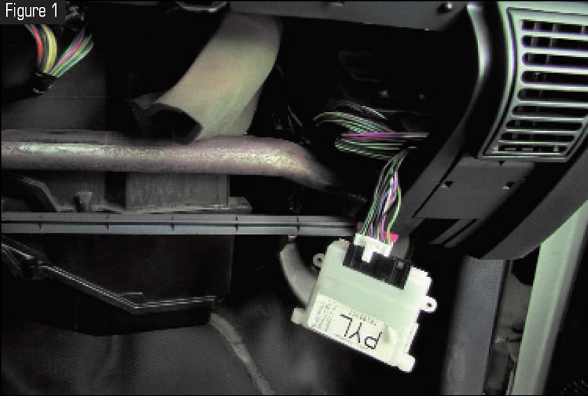
The speed buffer in a GM vehicle (see Figure 1) is a familiar piece of hardware for most transmission technicians. And its operation of taking an AC voltage signal from a speed sensor and converting it to a DC pulse signal for the computer is just as familiar. But what does come as a surprise to many is that Chrysler uses a similar speed-signal strategy for many of its passenger cars and vans.
Back in 1989 the original A604 transaxle had a vehicle-speed sensor (distance sensor) in the short axle housing. This signal was then hard-wired directly into the powertrain control module (PCM) and various other locations depending upon year, make and customized packaging. Additionally, the PCM would put this vehicle-speed signal out into the bus system for the various controllers on the network requiring the signal.
In 1993 all of this changed. The vehicle-speed sensor (VSS) in the short axle housing was eliminated, and output-shaft speed became the primary source for the vehicle-speed signal. Since the output-shaft speed sensor reads the main gearbox of the transaxle, for this to work properly the transmission control module (TCM) would need to be programmed to know the overall gear ratio of the transaxle (drive and driven, ring and pinion gears) and the tire size. This is the meaning of the term and process for “pinion factor,” and once this process is performed, the TCM has the necessary information to calculate vehicle speed properly. To get this data to the PCM, the TCM uses an internal speed buffer.
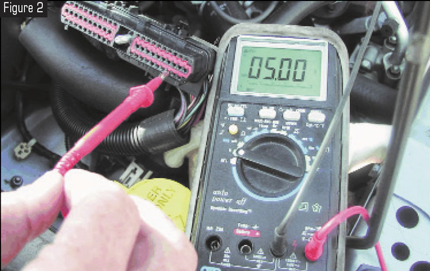
In the 1997 Caravan that we’re using as an example to observe the operation of the buffer circuit, the PCM provides a 5-volt signal wire from terminal 66 to the TCM on terminal 58 (see Figure 2).
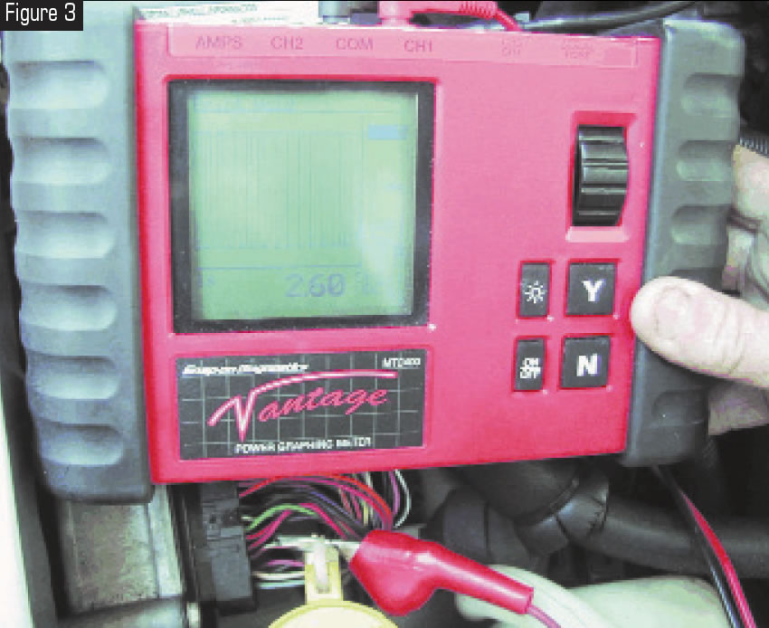
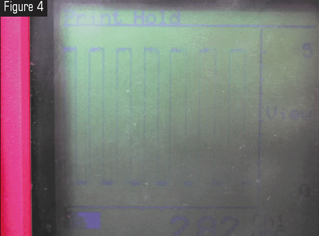
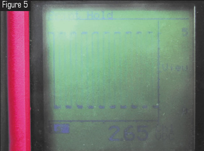
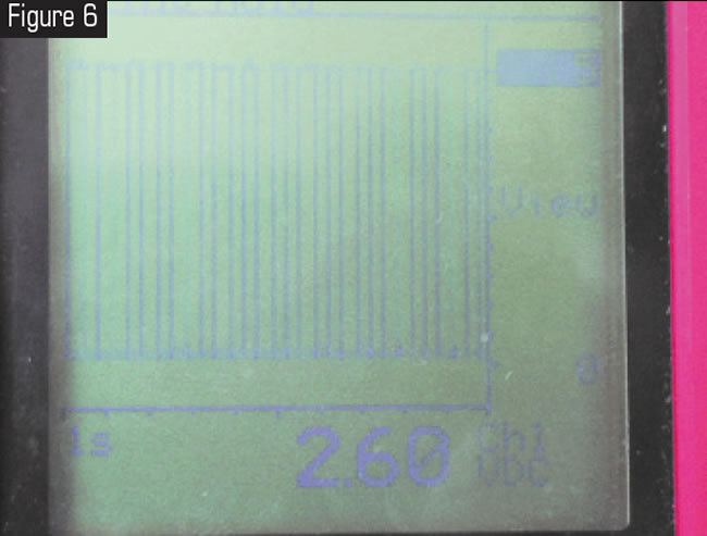
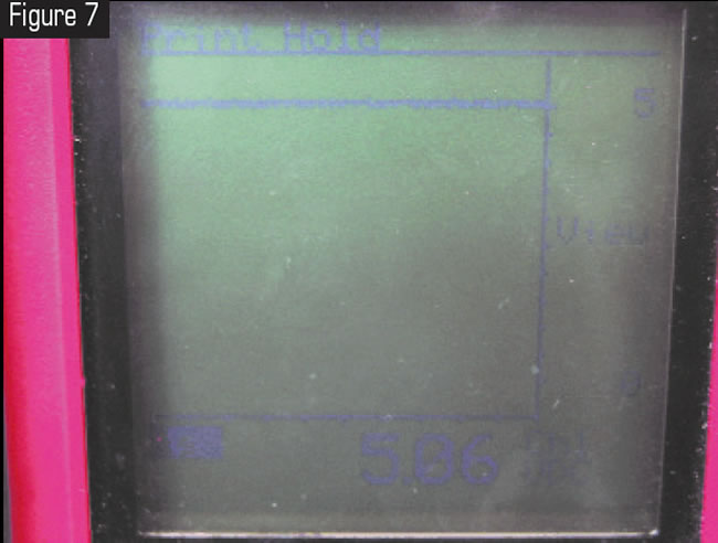
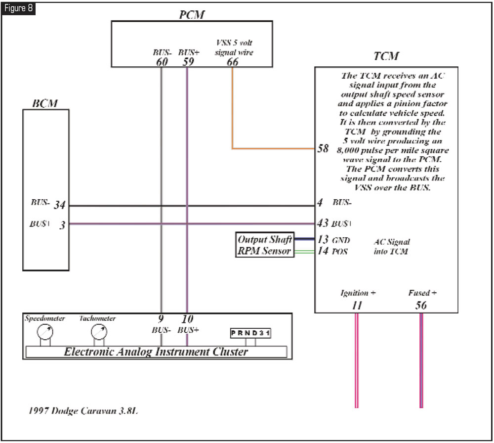
As the vehicle begins to move, the TCM provides the PCM with a square-wave signal proportional to vehicle speed by pulsing the 5-volt wire to ground (see figures 3 through 6). When the vehicle stops, the TCM releases the ground (see Figure 7). The PCM monitors and interprets this pulse into miles per hour, then broadcasts it over the communication network to all other modules requiring the signal. One such module is the electronic analog instrument cluster (see Figure 8). The data is received, interpreted and then presented through an electronic analog VSS gauge in the instrument cluster.
From this overview, it is easy to observe the many possibilities that could contribute to a loss of vehicle speed in the instrument panel. A powered-down TCM, a replacement TCM that has not received a pinion-factor flash and a faulty TCM are the most-common possibilities. A problem with the PCM or the electronic analog instrument cluster would be other possibilities.
If the TCM has not been replaced or powered down and the vehicle has a loss of vehicle-speed signal on the dash, you could make either of two quick checks to determine whether the TCM is the cause. One choice would be using a scan tool to check for a vehicle-speed signal from engine data. If the scan tool can observe the signal, the TCM is working. The other choice is to check the 5-volt wire for a pulse (refer to figures 3 through 7). If a pulse is observed in relationship to speed, then the TCM is working. At this point the PCM or instrument cluster may be faulty.
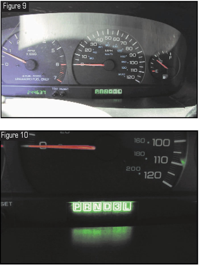
On vehicles equipped with a transmission range sensor, if the TCM is the cause for the lack of a vehicle-speed signal, this condition may be accompanied by illumination of all the lights on the PRND3L display (see figures 9 and 10).
You also may find that the TCM does not respond to a scan tool’s request for information (see Figure 11). All these problems usually result from a bad ignition switch or a broken wire causing a loss of ignition voltage at terminal 11 (see figures 8 and 12).
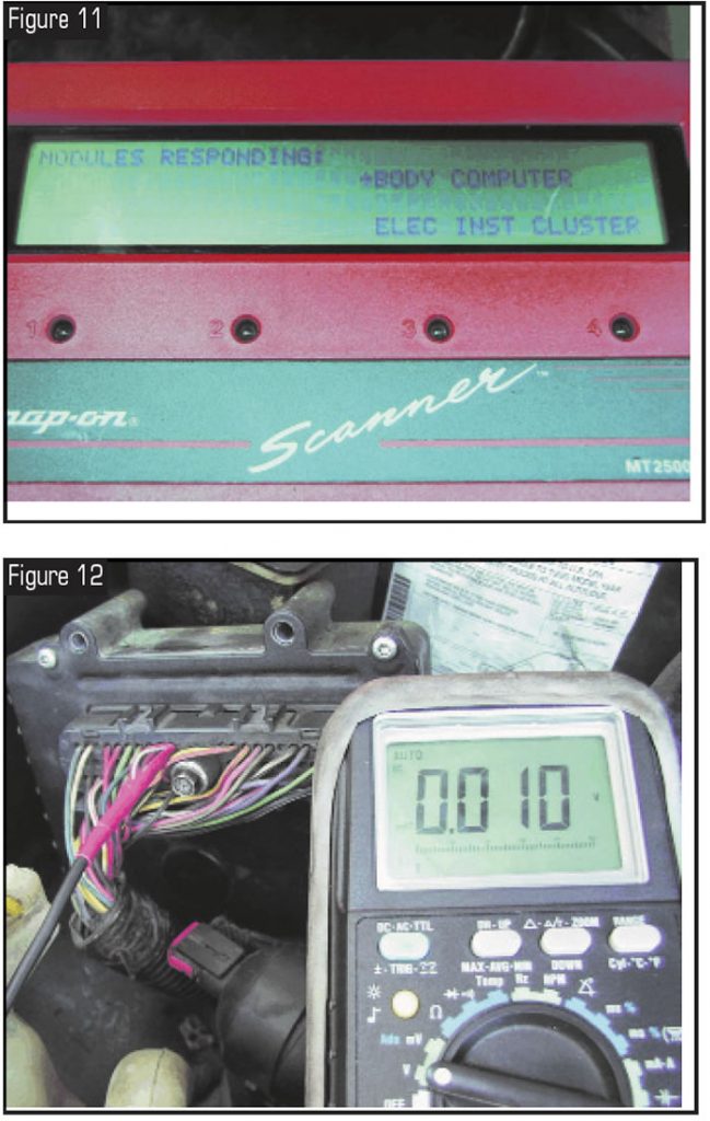
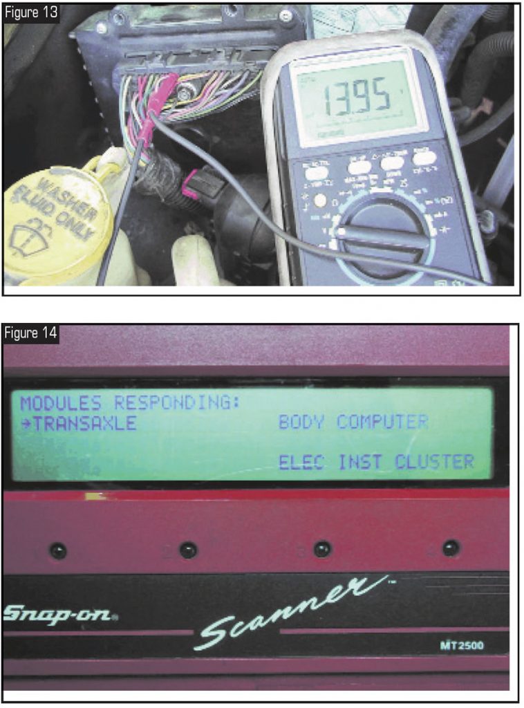
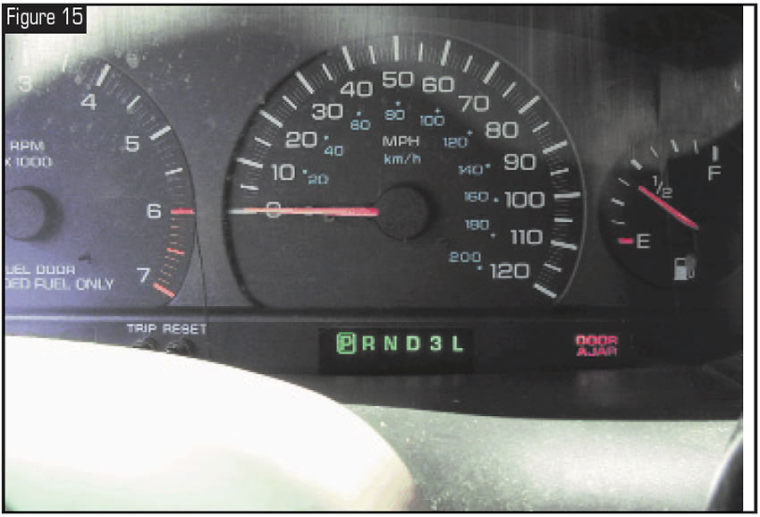
If this is the problem, a quick wire jump into terminal 11 from the positive post of the battery should cause all systems to return to normal, allowing for a road test to be performed (see figures 13 through 15). I have to say that this is not a fix, just a test. Once the road test verifies that all is well, remove the jumper wire before turning off the ignition. You then can begin having fun looking for the reason for the loss of voltage at terminal 11.
Instrument-Cluster Self-Diagnostic Test
Different degrees of self-diagnostic testing of the instrument cluster are available on many of Chrysler’s vehicles. To perform the test available with 1997 passenger vans, have the ignition switch in the off position. Press the TRIP and RESET buttons at the same time. While holding them down, turn the ignition to the on position. Continue to hold down the two buttons until the odometer window displays the word CODE. If a problem has not been detected, code 999 will be displayed. If the system detects a problem, it will display one or more of the following codes:
- 110 = Cluster Memory Fault
- 111 = Cluster Calibration Fault
- 905 = No CCD Bus Message from TCM
- 921 = Odometer fault from BCM
- 940 = No CCD Bus Message from PCM
After the codes are displayed, the instrument cluster will enter the following four sequential test modes:
- CHEC-0 = Dim Test – Instrument cluster light should dim
- CHEC-1 = Calibration Test – See chart below
- CHEC-2 = Odometer Test – Each digit should light
- CHEC-3 = Electronic Transmission Range Indicator Segment Test – Each segment of each digit should light.
These checks determine only whether the instrument cluster needs to be replaced. For example, when the instrument cluster enters the CHEC-1 calibration test, the first calibration check to be made is the vehicle-speed-signal gauge. The speedometer gauge needle should start at 0 mph and go to 20, then to 55 and then to 75 mph. If it does not, the instrument cluster will need to be replaced.
As mentioned in the main body of the article, after you have determined that the TCM is not the problem – leaving the PCM or instrument cluster as possibilities – this self-diagnostic test would be the next logical step. If code 940 comes up, we have strong evidence that the PCM may be the root cause. Voltage supply and grounds for the PCM would need to be checked and verified. If they are good, the PCM will need to be replaced.
CHEC-1 Calibration Gauge Test
Speedometer
1 0 mph
2 20 mph
3 55 mph
4 75 mph
Tachometer
1 0 rpm
2 1,000 rpm
3 3,000 rpm
4 6,000 rpm
Fuel Gauge
1 Empty
2 1⁄8 full
3 1⁄4 full
4 full
Temperature Gauge
1 Cool
2 Low Normal
3 High Normal
4 Hot


