Shift Pointers
- Subject: Intermittent problems related to the EATX relay circuit
- Units: 41TE, 42LE, 45RFE, 42RLE
- Essential Reading: Rebuilder, Diagnostician
- Author: Wayne Colonna, ATSG, Transmission Digest Technical Editor
Chrysler’s 41TE transmission has been in use since 1989, the 42LE since 1993, the 45RFE since 1999 and the 42RLE since 2003. With each of these transmissions having similar electronics, they also have similar diagnostic codes and testing consistencies.
This makes life a bit easier for the diagnostician, as he can count on the fact that no matter what vehicle comes through the door, terminal 56 at the transmission-control module (TCM) is the “hot-at-all-times” circuit; terminal 11 is the ignition power supply; terminal 15 is the EATX relay control; terminals 16 and 17 are EATX relay-output circuits; terminals 13, 14 and 54 are the input-/output-speed-sensor circuits; and so on.
And even within the past few years with the TCM and the engine-control module having been incorporated into a powertrain-control module (PCM), there are still similar consistencies here. C1-connector terminal 29 is hot at all times, and terminal 12 is the ignition power supply. In C4-connector terminal 18 is the EATX relay control, terminals 19 and 28 are the EATX relay-output circuits, and terminals 32, 33 and 34 are the input-/output-speed-sensor circuits. These consistencies give the technician something to rely on.
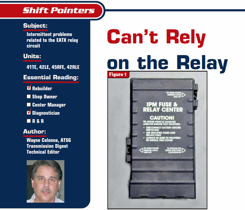
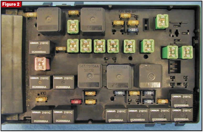
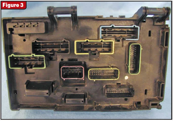
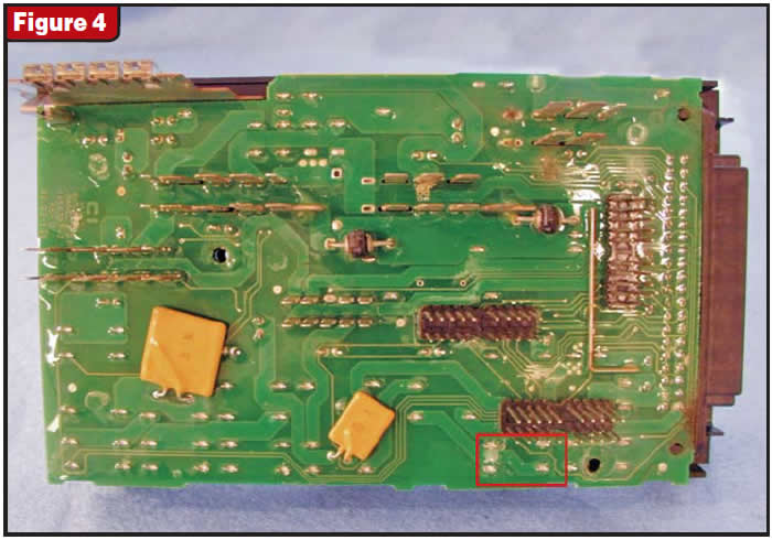
But a change over the past several years has caused erratic and inconsistent problems specifically related to the EATX relay circuit. It has to do with the use of an integrated power module, or IPM (see Figure 1). With the top cover off, you can see all the fuses and relays in Figure 2. This whole assembly can be removed easily, and on the underside of it you will find various connectors that plug into the vehicle’s system harness (see Figure 3). Once the assembly is out it can be further disassembled, as shown in Figure 4. Notice that this IPM is configured and constructed in such a manner that the relays and fuses make their connections through circuit boards. It is here that we are having intermittent and inconsistent problems as these circuit boards are failing, causing internal circuit faults that can drive just about any technician buggy.
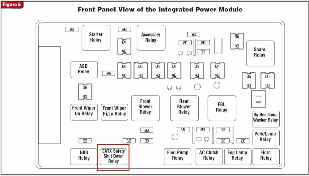
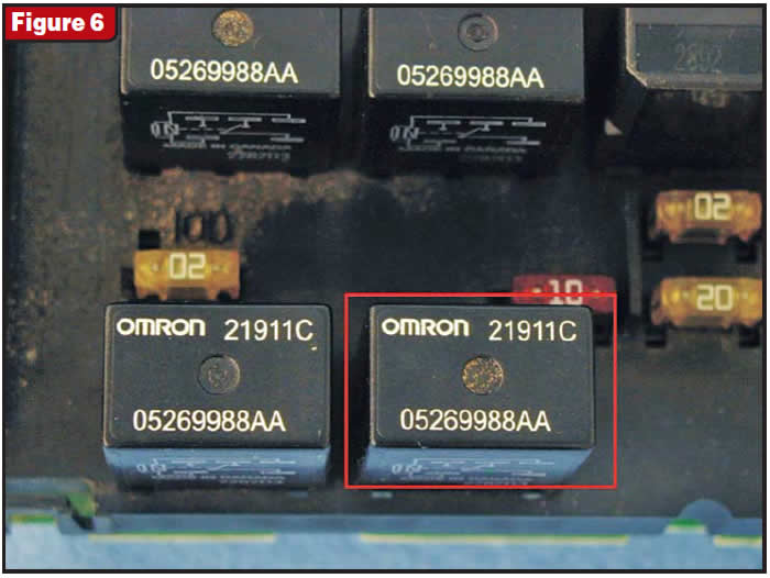
The example that I’m using for this article occurred in a late-model vehicle with a 41TE transmission that had defaulted to second gear in failsafe mode. A scan tool retrieved code 1768 (EATX relay stuck off), explaining the failsafe condition. Figures 5 and 6 show the location of this EATX relay in the IPM. Figure 7 is a bottom view identifying the four solder points to which the relay ultimately connects within the circuit board. The numbers shown in Figure 7 are actual numbers that you can see on the relay (see Figure 8), and by aligning the relay posts to the cavities they plug into, you can identify the four individual circuits (see Figure 9).
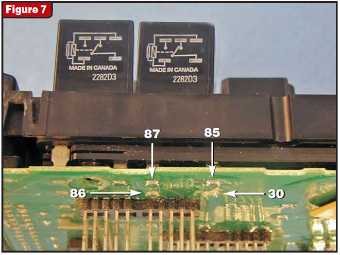
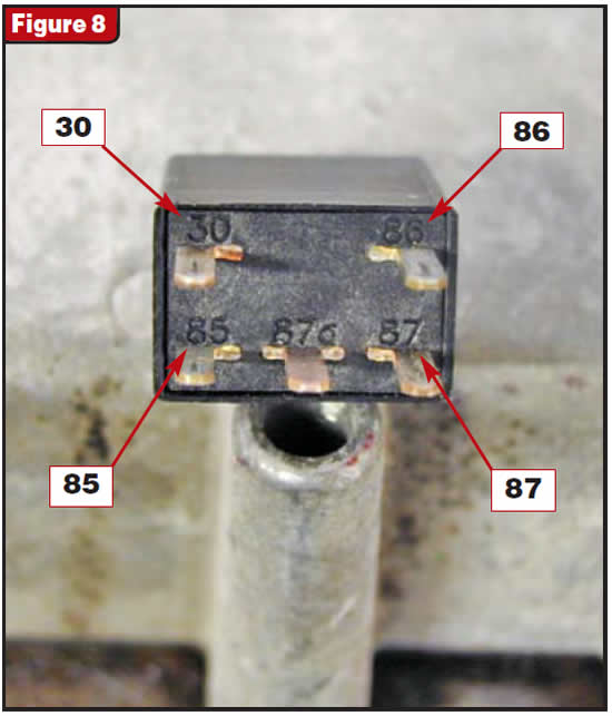
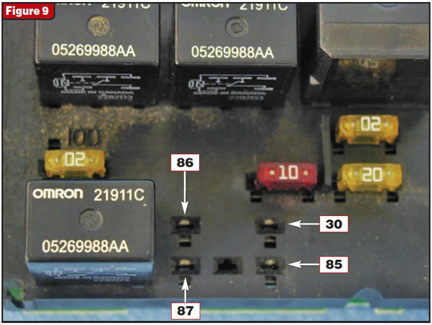
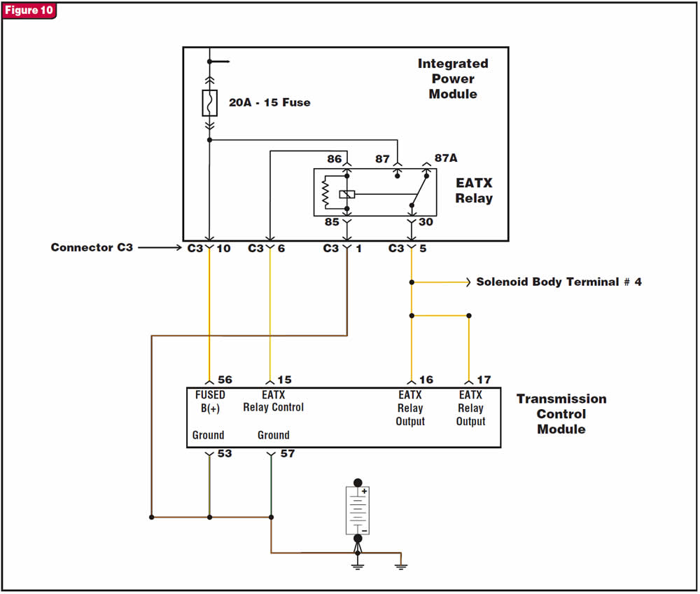
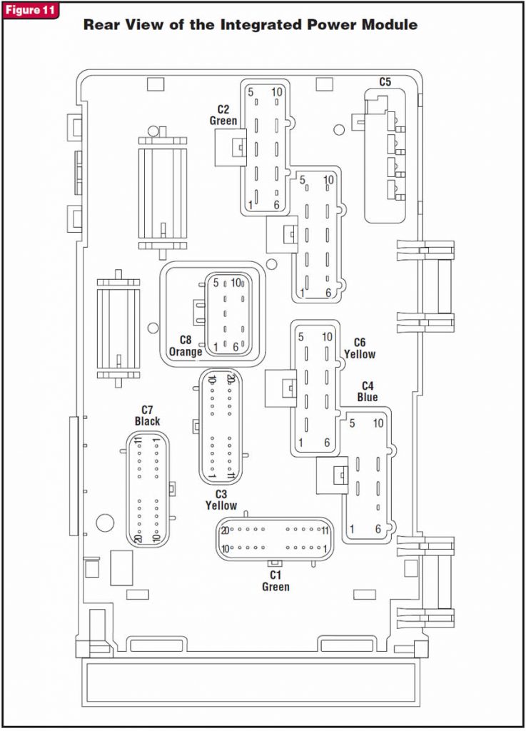
These numbers are quite significant, as they identify the function of each circuit in the relay, and you will find the numbers in a typical wiring diagram (see Figure 10). Post 86 is the power-to-coil circuit, post 85 is the coil’s ground path and post 87 is the power source to be switched to post 30 when the coil is energized. The wiring diagram also shows these circuits as they exit the IPM through connector C3. Figure 11 provides connector identification and location under the IPM box. As you can see in figures 3 and 11, this C3 connector is identified with yellow paint and has 20 terminals in it, but we are interested in only four of them: terminals 1, 5, 6 and 10.
Now remember, the problem with this vehicle was that the EATX relay was stuck off. This means that when the computer energized the coil, it did not see switched battery voltage at terminals 16 and 17. This could mean that the relay is defective, which would be the easiest solution. But with this IPM box, you cannot rely on the relay’s being the one and only simple solution – at least not when the customer is waiting for the car at 5:30 on a Friday night. It seems that the only time it could be this easy is when the customer doesn’t need the car right away and you have all the time you need. But if it is a “must deliver now” car or it belongs to a friend, a relative or your wife’s boss, that’s when things get tough.
So what are the other possibilities? If any of the relay’s four circuits develops an open, you certainly will have this condition. The first step in diagnosing this IPM fuse and relay box is to verify with an ohmmeter the four relay circuits where the posts enter the box to their respective solder points on the circuit board (see Figure 12). Once you have verified the integrity of each circuit from the relay side to the circuit-board side, each circuit will need to be verified from the solder points to their respective terminals in the C3 connector.
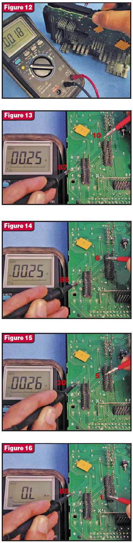
As shown in the wiring diagram in Figure 10, relay circuit 87 goes to terminal 10 in the C3 connector, circuit 86 goes to terminal 6, circuit 30 goes to terminal 5 and circuit 85 goes to terminal 1. Each of these circuits will need to be checked for continuity as shown in figures 13, 14, 15 and 16. You will notice that the last check shows an open circuit for the relay-coil ground path. This open circuit prevented the relay from energizing even though the coil was receiving power from the computer through circuit 86.
If every one of these circuits had checked good, then external wiring problems should be expected, but beware: We have seen instances of these circuit boards going bad intermittently, making it very difficult to find the problem. If the vehicle you are working on has erratic code setting and is equipped with an IPM, chances are the IPM is your problem, especially code 1768. Don’t rely on the relay; you could be very disappointed.
Thanks to the good folks at Cedar Grove Transmissions in Cedar Grove, N.J. – especially to Mike Miskowitz, who supplied me with the IPM to use for this article.
It could be possible to fix this IPM by carefully soldering a jumper wire in place from the #85 solder point to terminal 1 in the C3 connector, as the plastic cover does not go all the way down to the post base. This allows enough room to make this fix without causing cover interference. We are going to do the repair and send the box back to Cedar Grove to use on their next job. Maybe we will make their night at 5:30 on a Friday evening with a friend’s car.


