Technically Speaking
- Author: Jon Glatstein
46RE and 47RE units (and some 42/44RE units after 1996) use an interesting method to energize the coil of the transmission-control relay. As we all know, the switch part of the transmission-control relay is what provides battery power to the solenoids when its coil is energized.
The PCM controls the transmission-control relay by turning the ground for the relay’s coil on and off. What is interesting is the other side of the coil, where power comes in.
We are all familiar with the accessory power bus – all the circuits that become energized only when the key is in the ACC or RUN position. We also know about the ignition power bus, which is all the circuits that are energized only with the key in the RUN position. And, of course, there is the battery bus, which is on all the time. Well, in the 46RE/47RE units there is another power bus. It is not documented as a power bus, so it does not have an “official” name. Let’s call it the “Engine Running” bus.
Battery power to the Engine Running bus is provided by the PCM at pin 25 of connector 3 (see Figure 1) only when the engine is running. This is labeled “Generator Source,” because it actually is the source voltage for the generator’s field winding. Two other devices are connected to this same wire – the leak-detection pump in the evap system and the transmission-control relay.
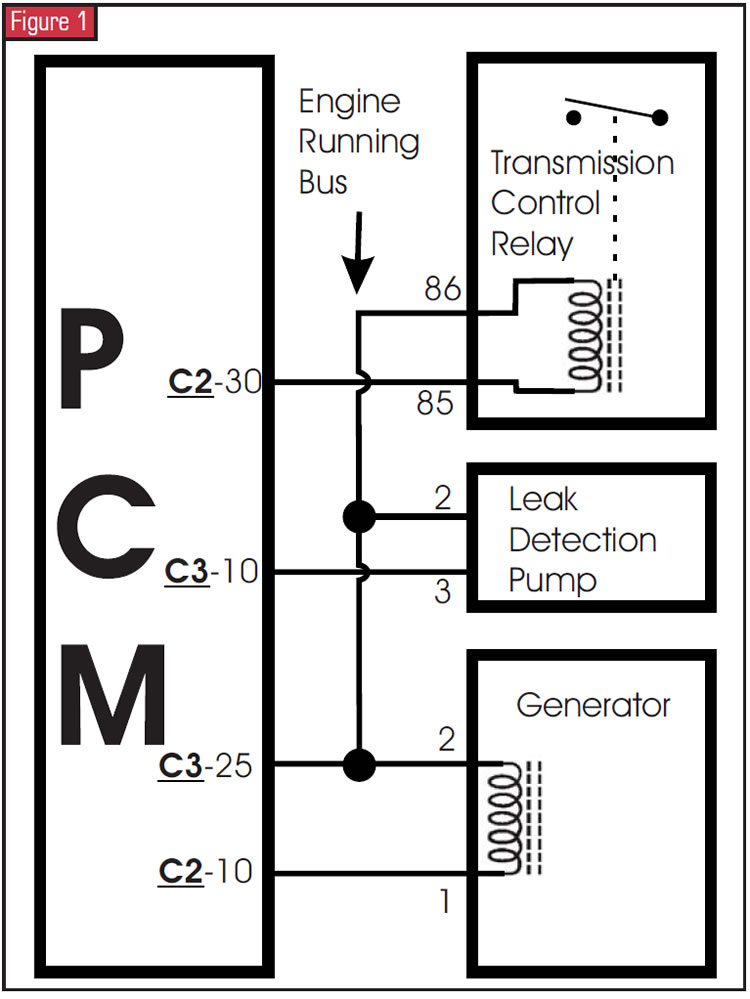
The electronic-voltage-regulator circuit inside the PCM energizes pin 25 of connector 3 only when the engine is running. The EVR controls the output of the generator by varying the pulse width of the generator field winding’s ground through pin 10 of connector 2, which DaimlerChrysler calls the “generator field driver.” This driver, like many other drivers in this PCM, controls ground.
This generator source voltage goes through two splices before it gets to the generator. At splice 116 it forks off to pin 86 of the transmission-control relay, which is one side of the relay’s coil. The other side of the relay’s coil goes to pin 85 and then connects to the PCM at pin 30 on connector 2, which is labeled “Transmission Control Relay Control.” This pin controls the transmission-control relay by turning the coil’s ground on and off.
The generator source wire also goes through splice 180, where it is tapped off to provide power to the leak-detection pump in the EVAP system. Electrically speaking, this pump operates the same way as the transmission-control-relay coil. Engine Running power comes in at pin 2, and pin 3 connects to the leak-detection pump’s solenoid control at pin 10 of connector 3 in the PCM.
So, if you do not see power to the transmission-control relay or the solenoids with the key on, try starting the engine. The same thing applies when you’re troubleshooting open-solenoid codes. If you see problems with the charging system, the evap system and the transmission at the same time, this “Engine Running” bus is the common element.
One additional note: In every wiring diagram I have ever seen for this circuit, the generator field winding is mislabeled; the plus and minus signs are placed incorrectly. Generator pin 2, which leads to the generator source pin at the PCM, should be labeled + and generator pin 1, which leads to the generator field driver pin at the PCM, should be labeled -. Often these plus and minus designations also are incorrect in the PCM part of the wiring diagram.

Jon Glatstein, a frequent contributing author to Transmission Digest, is a technical consultant and electronics specialist for ATSG and is also the ATSG Webmaster.


