Up to Standards
- Subject: Redesign of front drive axles
- Vehicle Applications: GM S, T & K trucks with four-wheel drive and independent front suspension
- Essential Reading: Rebuilder, Diagnostician
- Author: Mike Weinberg, Rockland Standard Gear Contributing Editor
In 1983 General Motors redesigned the front drive axles on its four-wheel-drive S and T trucks. The new design was an independent front suspension (IFS) for better handling and ease of manufacturing and repair. In 1988 GM added IFS front drive axles to its full-size-truck lines (K trucks).
We will call these units “front drive axles,” as terms like the “front rear” seem to confuse issues. When you are ordering parts it is easier to ask for a ring-and-pinion set for a front drive axle than for a front rear, which can sometimes result in your getting a gear set for a rear differential.
The front drive axle uses a ring and pinion that are cut to reverse rotation because of the forward placement. The IFS units use a ring-and-pinion/differential assembly housed in an aluminum case that is mounted to the truck frame and uses halfshafts with CV joints to get power to the front wheels. These units use an electrical disconnect for the front axle to ensure that the front wheels freewheel in 2WD for better fuel economy and less wear on the moving parts.
The IFS front drive axles are manufactured in four sizes that correspond to the widest part of the ring-gear diameter. 1983-2001 S and T trucks use a 7.25-inch ring gear. 2002-and-up S and T trucks and Trailblazer, Envoy and Bravada use the same-size ring gear but have a “pan mount” front drive axle, an arrangement whereby one of the axle shafts passes through the engine oil pan. The Hummer H3 uses a 7.6-inch ring gear in its front drive axle. The 1/2- and 3/4-ton K trucks have an 8.25-inch ring gear from 1988 to 2008, and the 1-ton HD-option vehicles use a 9.25-inch ring gear from 1988 to 2008 in vehicles equipped with 8.2-liter gasoline engines or diesel engines.
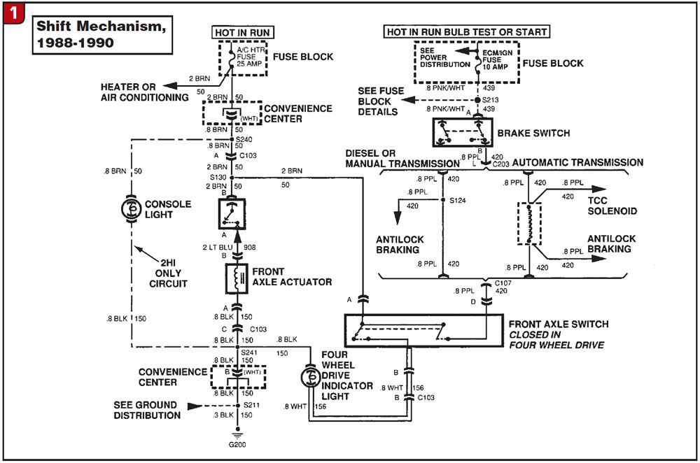
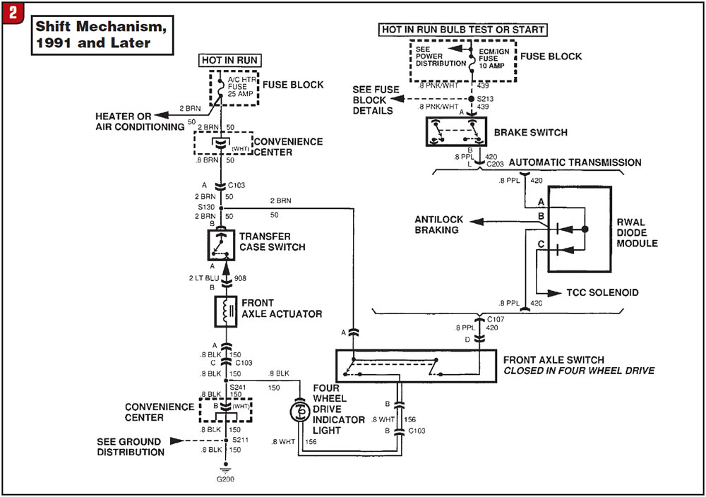
There is a problem with the front-drive-axle actuator, which is electronically controlled to engage 4WD when the transfer case is shifted into one of the 4WD ranges. From 1988 to 1990, these actuators had a silver metal body and two wires. These were replaced in 1991 and up with a black plastic-cased assembly having three wires. All the boxes for the parts I have seen had no wiring instructions or schematics on the three-wire system.
If you have to replace an early two-wire actuator with a late three-wire unit, here is the way to make it work. The three-wire assembly has two brown wires, one long and one short, and a black or blue wire. The short brown wire goes on the original positive side of the transfer-case switch. The long brown wire goes to the ignition on the 25-amp AC/heater fuse. The black or blue wire goes to ground. On 1998-and-up models, if the 4WD light continues to blink in 4WD, it’s usually an indication that the front axle did not connect.
A word of caution when you’re handling these components. The reason the earlier actuator was replaced was that the time it took to get into 4WD was too long. The black-bodied plastic replacement unit is a gas-actuated unit that engages very quickly. If you wish to put 12 volts to one of these units to test it, make sure it is installed on the axle and bolted in place. If you are holding one in your hand and actuate it with 12 volts, it will become a deadly weapon.
Figure 1 and Figure 2 above provide electrical schematics for both early and late actuation systems.
All the original-equipment GM ring-and-pinion and differential parts are manufactured by American Axle and Manufacturing (AAM). AAM uses the latest state-of-the-art gear-cutting processes, which I wrote about in an article in the May 2007 issue. The tolerances the company can hold are much improved over earlier methods of manufacture, and that has a big influence on your backlash setup when you’re replacing one of these ring-and-pinion sets.
These units all use screw-type adjusters to set ring-and-pinion backlash to specifications. If you’re using OE parts from AAM, they should be set to 0.004-0.006 inch of backlash. You can unscrew the vent-plug cover from the case to observe and measure the backlash. This is a much tighter spec than is usually found in other manufacturers’ product, so be careful if you are substituting aftermarket gears to follow the other manufacturer’s instructions on setup.
A second note here is to save the original pinion shim and use that to start your setup. Modern manufacture by AAM is so good that you will very rarely have to change from the original pinion shim, and by reusing it you will save quite a bit of time.
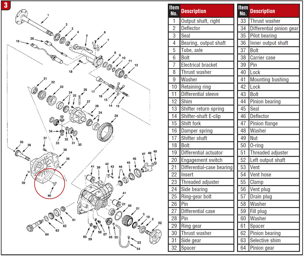
Getting back to the screw-type adjusters, they are typical spanner-type adjusters that are secured in position by small locking tabs. In the exploded view of the assembly in Figure 3, the locking tab is # 40, and two are required. Do not reuse the old locking tabs during rebuild. They typically will be bent, and you risk fatigue cracks if you try to straighten them. If they should crack after rebuild, the adjuster will move off its setting and will quickly cause the ring and pinion to fail. The lock tabs cost $5 and are a good safeguard for your reputation and your wallet.
With the current state of the economy and fuel prices you will have many customers who would like to change ratios in their trucks to achieve better mileage. The IFS front drive axle is no more difficult to set up than any other unit. Make sure that the ratios on the front drive axle and the rear axle match and add to your bottom line.