TASC Force Tips
- Author: Bob Warnke
Isolating the loss of reverse or TCC concerns
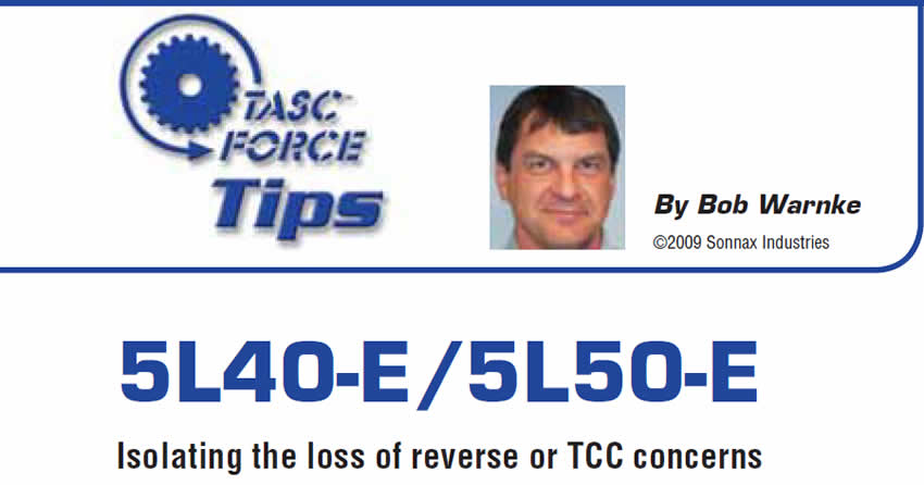
Figure 1 shows a 5L40E valve body being tested on a valve-body machine. The pressure used here is lower than normal operating pressures, but that made it possible to capture the many spurts and geysers erupting from the valve body. In reality, under normal operation, these spurts would be a pressurized spray. There are many exhaust points in modern valve bodies, and even under the best of circumstances this flying fluid traps and carries a fair amount of air with it on its way to the sump. This is expected, and sumps and pickups are designed to deal with a certain amount of aeration.
As valves and bores begin to wear and allow leakage, the easiest path for the leak is to exhaust. Two things happen as a result of this wear-induced exhaust leak. First, the leak allows a pressure drop, which is loss of control pressure. Valves or components no longer move, apply or respond as intended. Second, the amount of exhausted fluid and, therefore, the amount of air entering the sump are increased. The amount of aeration can easily surpass the sump’s ability to dissipate the air before the pump picks it up. The minimal sump capacity of the 5L40-E makes it especially vulnerable to this problem.
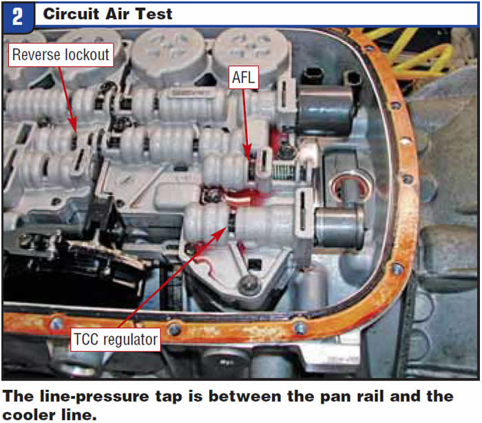
The chart below identifies reverse or TCC complaints associated with the two-pronged ailment created by wear and leakage. The illustrations and notes are in the order of service, beginning with in-vehicle, on to disassembly and bench inspection and ending with the preparation for dynamometer or vehicle testing.
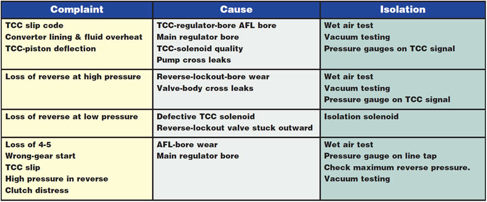
Circuit air test
With the oil pan removed and the manual valve in the reverse position, apply 30 to 40 psi of regulated air into the main line-pressure tap (Figure 2). This is referred to as a captive wet air test or WAT. The tap is between the pan rail and the cooler lines. A good valve body will have minimal fluid loss at the three locations indicated.
Loss of reverse at low pressure
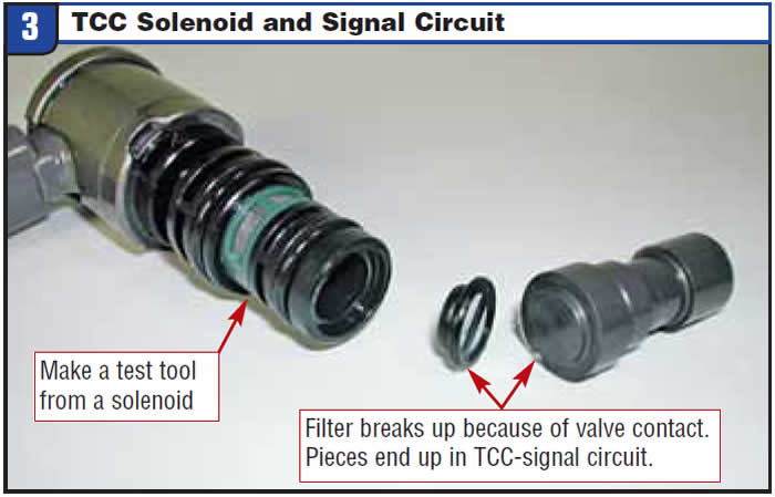
It is common for the filter to eventually break as a result of contact with the valve. Filter fragments migrate to the reverse-lockout bore and cause the valve to stick toward the retainer.
Loss of reverse at high pressure
Cross leakage into the TCC signal circuit can partially stroke the reverse-lockout and TCC-enable valves. Cross leaks may occur at the pump surface, TCC solenoid, TCC regulator bore, a warped valve-body surface or the reverse-lockout valve. When TCC-signal-circuit pressure reaches 5-7 psi, the reverse-lockout valve will have moved enough to restrict reverse. At 10-12 psi the TCC-control and enable valves are positioned to restrict flow of converter-release oil.
A used TCC solenoid can be modified for a test tool (Figure 3), or a fixture can be made to duplicate the OE manifold. To use a solenoid, remove the coil and both screens, and then plug the port that had the wrapped screen. If you can make your own test manifold, make a through-hole that exits at the TCC valve and tap the outer end for a removable plug. This tool can be used in a functioning unit, so a removable end plug allows you to verify pressure buildup.
Using the test tool on a bench unit, apply low air pressure to the outer end. Air flow should exit only at the TCC regulator valve and into the TCC signal circuit.
During the air test, the TCC-enable valves (in the pump) and reverse lockout should stroke, and you should see no leakage should at the TCC-regulator bore. If the reverse-lockout valve does not stroke, filter particles may be causing it to stick.
If you use the tool during a vehicle reverse-pressure test, it can isolate valve-body vs. pump issues. Install your test manifold, with the removable plug in the through-hole. If reverse remains engaged at high pressure, the original TCC solenoid had a cross leak. If reverse is still lost, the unit has a cross leak and circuits can be air tested through the tool to identify the source.
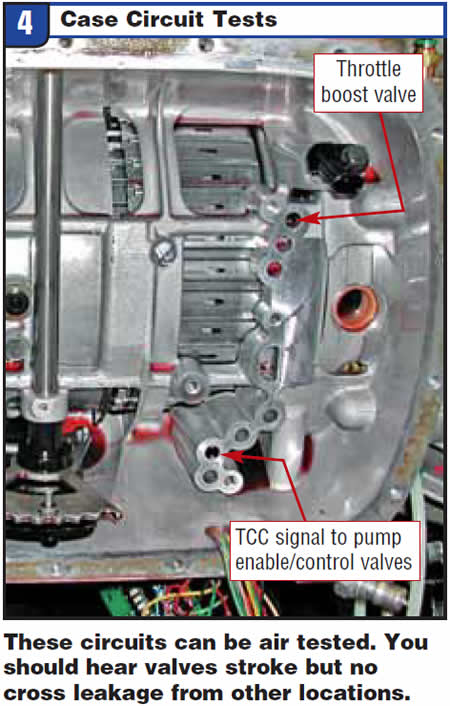
Case circuit testing
The case circuits shown in Figure 4 can be air tested to identify pump cross leakage. Both circuits are dead-ended at the valves. When they are pressurized at 50-70 psi the valves should stroke, but you should see no leakage from any other area. If it does leak, there is bore wear or pump warpage, which leads to TCC and clutch-pressure problems.
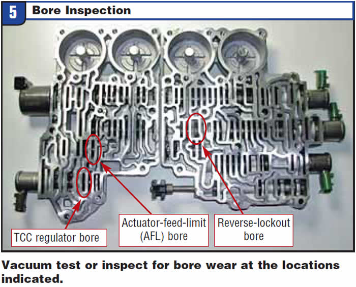
Valve-body bore inspection
Figure 5 identifies valves of concern that have been isolated in previous tests. Once the casting is cleaned, these areas can be vacuum tested or the bore can be inspected for wear. The valves themselves rarely have any witness marks. Bore wear can be detected, but it does require careful inspection. With a calibrated vacuum test station and proper valve-to-bore clearance, these circuits should retain at least 18 inches of vacuum.
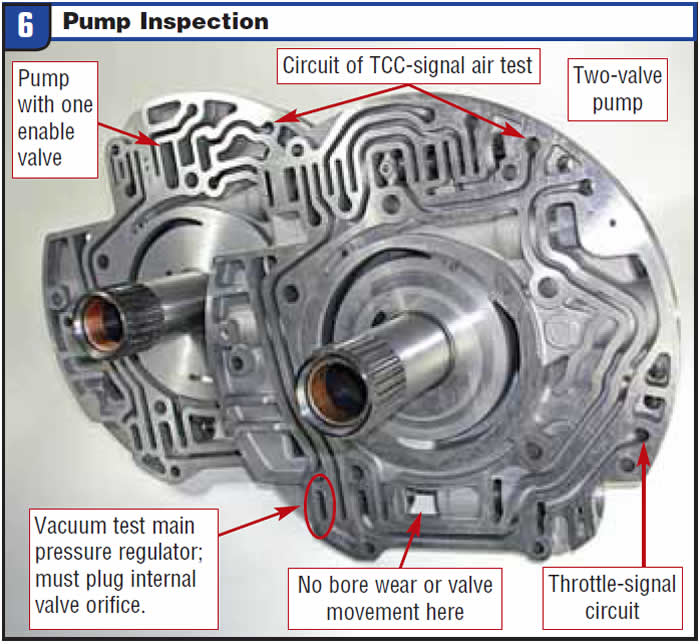
Pump inspection
Once the unit has been disassembled, inspect the TCC-enable bore and main pressure-regulator bore (Figure 6). Main-regulator-bore wear causes slide instability, pump/rotor damage, high pressure and TCC issues. Bore wear at the TCC-enable valves’ inner spool causes overheated converters and high slip rates.
Bellhousing pressure taps
If you have repetitive problems, or wish to verify TCC-solenoid quality and control, tapping into the TCC circuit at the case bell (Figure 7) will be a productive test. Tapping into these circuits identifies the amount of pressure within the TCC apply and signal oil.
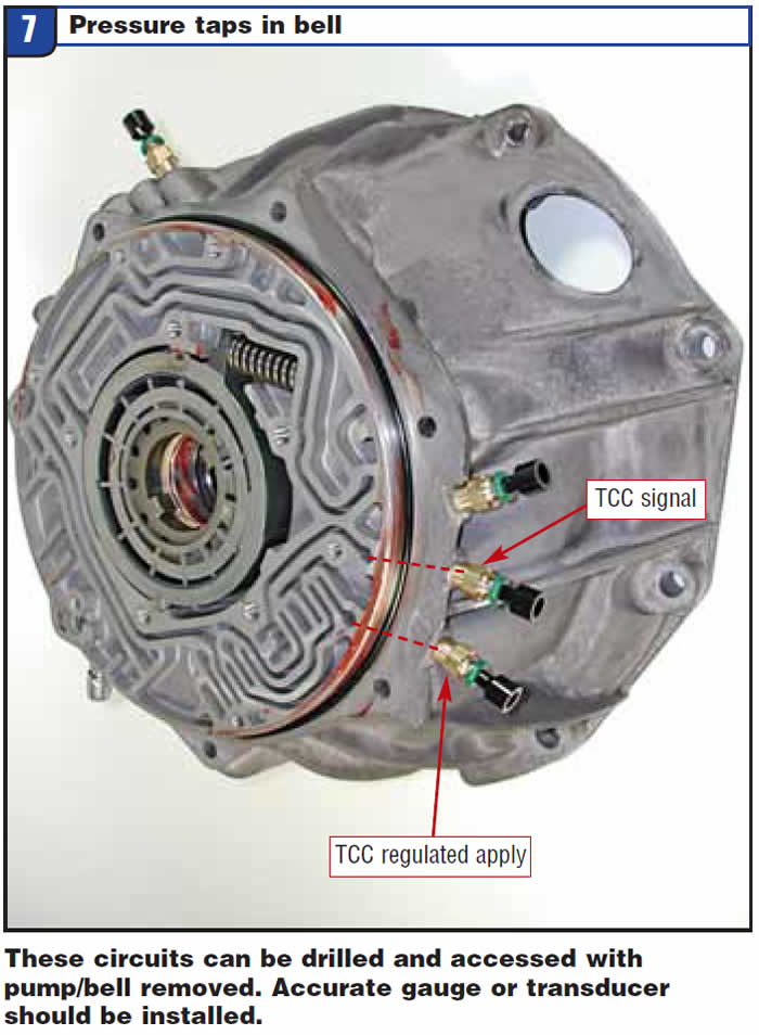
If you perform this test, use the precaution of the construction trade: “Measure twice and drill once.” The casting material is minimal but sufficient to access the ports with a Parker # 169PL-4-10X32 fitting. If you have not used this nylon-tubing test before, also buy a 169PL-4-2 and sufficient nylon tubing.

Bob Warnke is Sonnax vice president of technical development and a member of the Sonnax TASC Force (Technical Automotive Specialties Committee), a group of recognized industry technical specialists, transmission rebuilders and Sonnax Industries Inc. technicians.


