Up to Standards
- Author: Mike Weinberg, Contributing Editor
The transmission-repair industry is all about gears. The word transmission means transmitting or sending, and that is exactly what an automotive transmission does. The transmission sends the power produced as torque (turning force) by the engine and transmits it in a usable form to the driving wheels.
This seems to be simple enough until you look at the variety of technology employed in this process. The discussion here is about the technology employed in standard-transmission gears, the basic understanding of which will answer many questions encountered in the repair of automotive and truck gearboxes.
Making the torque produced by the engine usable requires multiplying or reducing that torque as it is transferred to the driving wheels, depending on the driving conditions encountered. We all know this as the different speeds available in a given transmission. From a standstill or very low speeds, we need to multiply the engine torque available to get the mass of the vehicle into motion. At highway speeds, less torque and less engine speed are needed to maintain a given road speed, with a resulting savings in fuel.
As an example, to break the average full-size car away from a dead stop probably requires about 150 horsepower. To maintain 60 mph on flat ground requires about 15 horsepower. All this is possible because of the flexibility available through the different speeds or ratios available in the transmission.
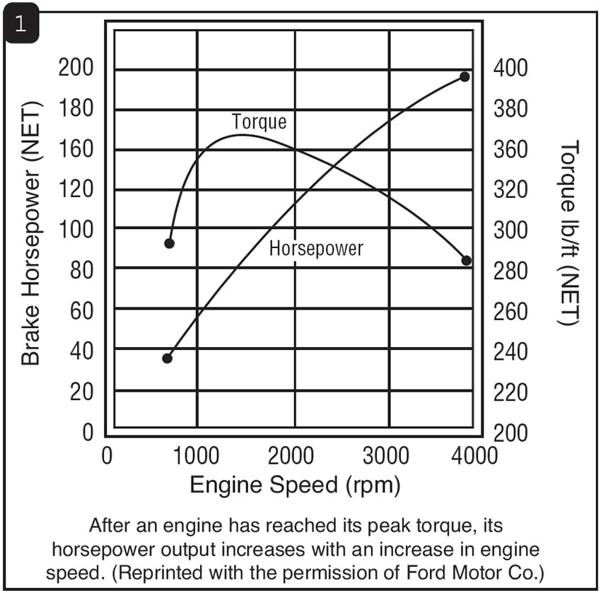
Every engine produces power, which illustrated on paper shows up as a curve on a graph (see Figure 1). This is known as the power band of the engine. The transmission ratios must be matched to that curve, and drivability is dependent on the weight of the vehicle, the final-drive ratio, size of tires and wheels, and the ratios of the transmission.
Typical gasoline engines have a fairly wide power band, For example, a 350-cubic-inch engine will produce usable power from 1,000 to 5,500 rpm, and the peak torque or power will be generated at roughly 3,500 rpm. Diesel engines have a much narrower power band, usually in the range of 1,000-3,000 rpm, which is why you see 13-speed transmissions and two-speed differentials in heavy over-the-road trucks. This is necessary because the engine “runs out of revs” very quickly, so more speeds are required in the gearbox to keep the engine in the power band while road speed increases to highway speeds. (See Figure 1 for a typical torque curve).
Gears are the finest method of altering the speed or torque of a rotating shaft. There are a variety of different types of gears, which we will look at as we go on, but it is important to understand how different speeds or ratios are achieved through the size of the gears.
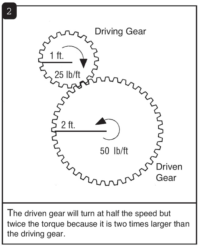
Gears have teeth in numbers proportional to their diameters. If one gear is twice the size of the other gear, it will have twice as many teeth. If one gear has 10 teeth and the opposing meshed gear has 20 teeth, the larger gear will rotate at half the speed of the smaller gear (see Figure 2). Consider the smaller gear as the driving member and the larger gear as the driven member; one turn of the small gear will result in half a turn of the larger gear. This setup will produce a ratio of 2-1.
To calculate a gear ratio, we must divide the number of teeth on the driven gear by the number of teeth on the drive gear. To figure the ratios in a transmission, we first must obtain the input ratio, dividing the tooth count of the input or main drive gear into the tooth count of the meshing gear on the countershaft. Now we have to divide the number of teeth on the countershaft into the number of teeth on the matching speed gear. Once you have obtained those two ratios, you multiply one by the other to get the ratio of the transmission for a given speed.
Other factors that will come into play include the actual size of the gears, as the larger one gear is in relation to the driving gear, the greater the torque capacity of the gearset. Looking at a transmission in relation to the size of the geartrain will help you identify which speed gear is which. A 1st-speed gear is always larger in diameter than a 2nd-speed gear, and a 3rd-speed gear is always smaller in diameter than a 2nd-speed gear etc.
Different types of gears are used in different types of transmissions (see Figure 3). The easiest gears to design and manufacture are spur or straight-cut gears, in which the teeth are straight and parallel to the shafts in the transmission. These are immensely strong gearsets that produce little or no thrust loads and are used in common transmissions in the reverse gearset. Getting a shaft to run in the opposite direction or reverse rotation requires adding a third gear to change the shaft direction. The drawback to spur gears is that they are noisy. The only transmissions that use spur-cut gears today are racing units and some heavy-duty truck transmissions, in which noise levels are not a concern.
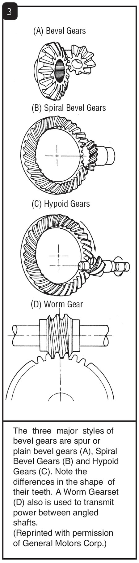
The next type of gears commonly encountered is bevel gears. Bevel gears are common in differentials as “spider gears” and run at 90° angles to each other. They are cut at an angle but are straight-cut gears.
Then there are spiral bevel gears, which also run at a 90° angle to each other but have a spiral cut to the bevel. These gears are most common in power-transfer boxes used to create all-wheel drive in modern transmissions such as the one in a Mitsubishi 3000 GT.
In rear-wheel-drive vehicles the differential uses hypoid gears. This is the most-common form of ring-and-pinion gears on which we work. Hypoid gears have a spiral cut, but the pinion gear is mounted below the centerline of the ring gear. These gears are machined very precisely to operate extremely quietly.
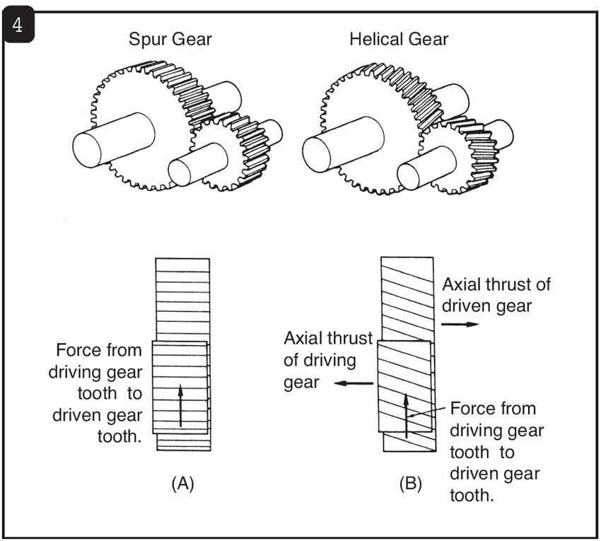
The gear design of choice for the modern transmission is the helical-cut gear. All passenger cars and trucks of modern design use helical gears, which are cut on a curving slant and operate extremely quietly. The drawback to this design is the cost of manufacture and the thrust loads these gears produce in operation. By design, helical-cut gears tend to try to move away from each other because of the angles of the cut as engine torque increases and tend to move together as throttle opening is decreased (see Figure 4). This design requires stronger case designs and better bearing support to handle the thrust generated that causes the shafts to want to “walk” away from each other. In most late-model transmission designs, the reverse gearsets are of helical design to ensure a quiet reverse operation.
The final type of gearing in some cars is the worm-gear design, commonly used in steering boxes and some speedometer applications. With the increase in rack-and-pinion steering systems, worm gears are going the way of the dinosaur.
The technology that goes into the design and manufacture of a helical gear could fill a book by itself. The fact that we can buy quality gearsets relatively inexpensively is testimony to the manufacturing capabilities of the transmission and drivetrain manufacturers. Understanding the design and nature of the gears you are working on will help you in identification and problem solving. If you are interested in reading to further your knowledge, Manual Drive Trains and Axles by Thomas Birch is an excellent book on this subject. The publisher is Prentice Hall (www.prenhall.com). Another must-read book is Today’s Technician, Manual Transmissions and Transaxles by Jack Erjavec, published by Delmar Publishers (www.delmar.com/delmar.html). Reading these books thoroughly, paying particular attention to the theory sections, is the equivalent to a year’s worth of college. The day we stop learning is the day we begin to move backward.