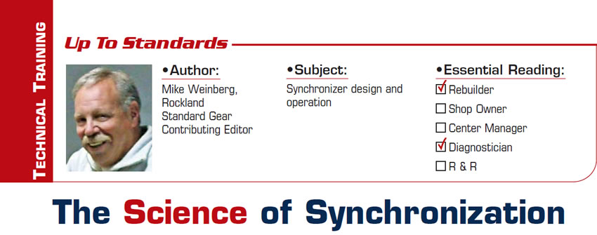
Up to Standards
- Subject: Synchronizer design and operation
- Essential Reading: Rebuilder, Diagnostician
- Author: Mike Weinberg, Rockland Standard Gear, Contributing Editor
In the early days of automobile design, the transmissions were non-synchronized, and the driver had to match the shaft speeds in the transmission to the vehicle road speed by double-clutching. Double-clutch shifting means that as the driver is selecting a desired gear at speed, the clutch is depressed, the shift lever is moved to the neutral position, the driver then engages the clutch and blips the throttle to match engine speed to the rotational speed of the driveshaft, and then depresses the clutch again and moves the shift lever into the desired gear.
This still takes place in race cars and some heavy-duty-truck applications. Obviously, this requires a high skill level from the driver, and any mistakes cause transmission damage and accelerated wear on the speed gears and sliding sleeves.
The next step in the design was synchronization. To synchronize means to coordinate several events to take place at the same time. Soldiers synchronize their watches before a mission to make sure everyone is on the same time schedule. Synchronized transmissions are easy to use, eliminating the driver’s having to match shaft speeds for each shift and creating a smooth, clash-free gear engagement with only a clutch release necessary. Synchronizers are one of the most-misunderstood parts of the transmission, and as with zippers everyone knows how to use one but most people have little or no clue as to how they work.
The basics of synchronizing the transmission shift are simple. The components of the synchronizer consist of a hub that is splined to the mainshaft, which has a sliding sleeve splined to it. The shift fork rides in the sliding sleeve. Within the synchronizer assembly are keys (struts, dogs) that move with the sliding sleeve to engage a synchronizer or blocking ring. The blocking ring or synchro ring is a wet clutch. As the sliding sleeve moves the keys forward, the synchro ring then presses on the cone of the speed gear, which is freewheeling on the mainshaft, to slow it down or speed it up to match the shaft speeds.
The synchro ring has external teeth that match the engagement teeth on the speed gear, and until these teeth line up the shift is blocked. As the shaft speeds equalize, the blocking ring (synchro ring) relaxes and rotates laterally to permit the slider to engage the speed gear, locking the speed gear to the mainshaft, and the shift is completed (Figure 1).
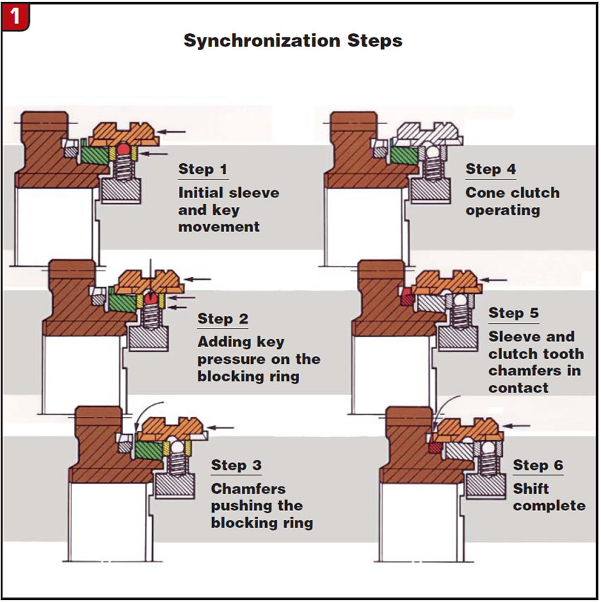
For this to happen correctly, an element of timing is required. First, the clutch needs to be completely released, disconnecting the input shaft from the rotation of the engine. The input shaft is not connected to the mainshaft, but the mainshaft is always connected to the driveshaft, and when the clutch is depressed (disengaged), the driving wheels are moving the mainshaft at road speed while engine speed is dropping.
The greatest single cause of synchronizer damage or hard shifting comes from a clutch that is not releasing fully. You must have a 0.050-inch air gap between the disc and the pressure plate when the clutch is fully depressed. Other issues such as short-throw shifters, incorrect fluid fill (either too much fluid or a fluid not of the correct viscosity) will change the synchronizer timing and create notchy, grinding or blocked-out shifts.
The early-design synchronizer rings were made of brass or bronze. They had threads cut into the inner surface that engages the cone of the speed gear to help exhaust the transmission fluid from the cone surface of the speed gear to create a higher level of friction. Brass and bronze worked well with the older, low-revving engines that did not have a great deal of horsepower. They did suffer from increased wear on the inner cones of the rings and on the slots in the rings that the keys went into because of the softer brass running against harder steel components.
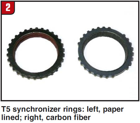
The vastly improved power and efficiency of later-model engines created a need for improved synchronizer material. The first new design was BorgWarner’s paper-lined rings (Figure 2) used in the T5 five-speed transmissions. Using a paper lining very similar to automatic-transmission clutch material, BorgWarner created a very smooth-shifting design suited to the muscle cars of the day.
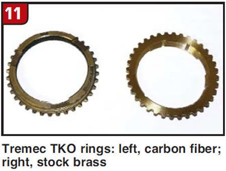
As manufacturers increased the horsepower and torque of the engines with improvements such as fuel injection and turbocharging, the power exceeded the paper-lined rings’ capacity. The next evolution was to carbon-fiber-lined rings (Figure 2), which are still in use today. The Tremec T56 six-speed transmission started with paper-lined rings and then switched to carbon fiber.
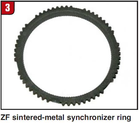
Synchro rings are now made with sintered-metal linings (Figure 3), as used by ZF and Getrag present-day designs. These rings are very aggressive and can have an adverse wear effect on the cones of the speed gears. You cannot accurately measure a taper. Whenever you are working with these rings it would be wise to make sure the cones of the speed gears are not worn out. Using a permanent black marker, coat the cone on the speed gear. Then twist a new or known-good ring down onto the cone and look at the pattern it leaves. A good cone should show an even wear pattern all around the cone, and even from top to bottom. On a bad gear you will see skips, open patches, or a pattern that is good on only part of the whole cone. Replace that gear before it comes back to haunt you.
As power increased further the need for heavier synchro capacity increased. The general strength of a transmission is measured by the distance from the centerline of the input shaft to the centerline of the countershaft, which tells you how large the gear diameter can be. With the old-style synchro-ring design, the diameter of the gears would have to be increased to have a larger synchronizer ring, which is counterproductive in a world that is thriving on fuel economy, lighter weight and smaller vehicles.
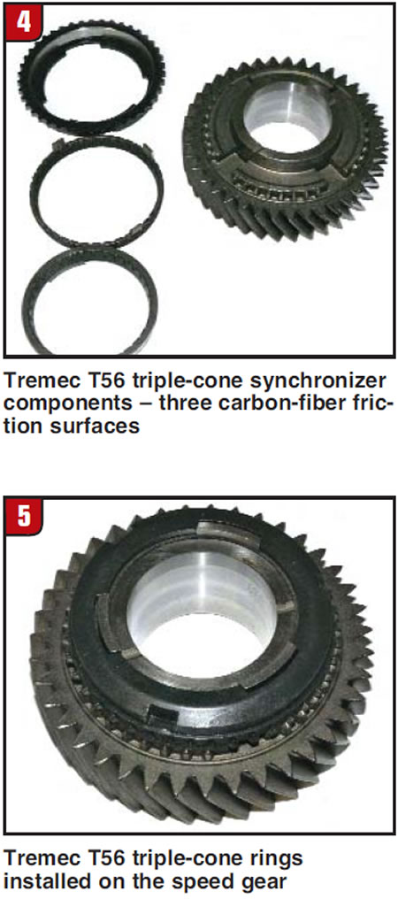
The next step of the design evolution is double- and triple-cone rings, which are now common. This gives the friction area of the ring double or triple the single-cone capacity for torque without increasing the gear diameters. Tremec has been at the cutting edge of this move with the T56 and Magnum transmissions, which are all supplied in high-performance vehicles such as Mustang, Corvette, Cadillac CTS-V, Pontiac GTO, Dodge Viper and Challenger, and the new Chevy Camaro. Figures 4 and 5 show how in the same space the ring capacity is increased.
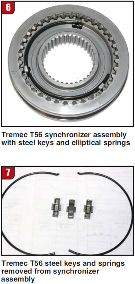
The next area of improvement has been the synchro keys and the retention method to hold them in place on the sliding sleeve. Past designs almost always used two circular spring-steel rings with stamped-steel or solid synchro keys (figures 6 & 7). Heat of long-term operating cycles weakened spring tension and made more inconsistency in shift feel.
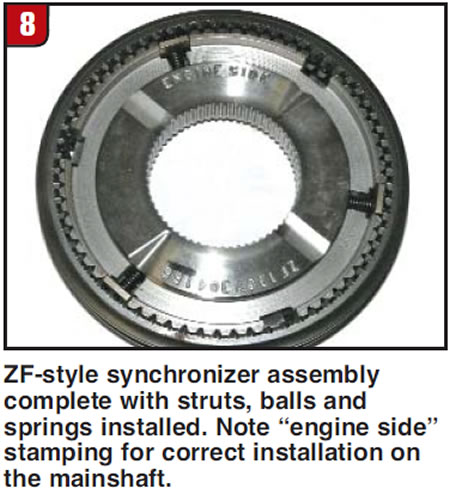
The next design step was a system of struts with a ball-and-spring arrangement that centered the ball in the strut, as you can see in the ZF synchro in Figure 8.
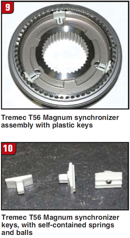
Tremec further enhanced this design in its new T56 Magnum design, using a plastic strut with the ball and spring trapped in the plastic (figures 9 and 10), making assembly and service much easier. Another added benefit of these designs is the elimination of broken keys. Units that have bad clutch release are not disconnecting the engine from the input gear when a shift is made. The keys are struggling against a torque load that should not be there and ultimately will break. If this happens after the shift is completed, it is common for pieces of the broken key to prevent the driver from shifting back out of the gear, making the car undrivable.
Another neglected area of focus with regard to synchronization is the transmission lubricant. Back in the days of brass rings most transmissions used 90-weight gear oil.
The car manufacturers would get numerous complaints about high shift effort in cold-weather driving because of the high oil viscosity until the unit reached operating temperature. This caused many vehicle manufacturers to specify ATF for the lube fill, which removed many of the cold-shift headaches and did not affect gear wear.
Today every synchronizer ring is specified to run with a specific fluid. Make sure that you are using the correct fluid, as the shift problems will he nasty with the wrong stuff. If you put an incorrect fluid into a fresh rebuild, the lining on the rings will soak it up and be unable to apply friction to the speed gears correctly. You might be able to drive it out by replacing the oil and traveling a few hundred miles, or you may have to go back in and replace the rings.
The new-material rings also can make noise because of an incorrect oil. The Dodge Neon transmissions used a very specific oil and were famous for chirping in neutral if an incorrect lube was used. Carbon-fiber rings are sensitive to certain additives in some brands of fluid, which attack the linings.
There are many things that affect synchronizer performance, starting with the clutch. Wear on shifters, bushings, shift forks, rails and pads, and internal endplay within the transmission will all cause a variety of shift problems.
One often-unmentioned problem is the driver. The car owner is the one element that you cannot control but can check out. A smart move is to have the driver take you for a ride after he has paid for the repairs. You can say you want to make sure he is happy and satisfied, but you can now get a look at how what you are warranting is going to be handled. Does he downshift instead of using the brakes to slow the car? Brakes are cheaper than transmission repairs and you can respectfully suggest that to him. Does he rush his shifts, ride the clutch, leave a traffic light at 5,000 rpm? You can learn an awful lot in a 10-minute drive.