Up To Standards
- Author: Mike Weinberg, Contributing Editor
Manual-shift transmissions have been manufactured with synchronized gear train for decades. The early designs were three-speed transmissions with 2nd and 3rd gears synchronized, and as transmission design progressed, four-, five- and six-speed transmissions were developed. At this point all forward speeds were commonly synchronized, and as the purchase costs of the vehicles increased and customers became more demanding, reverse was synchronized in most late-model vehicles. Synchronizers remain the most-misunderstood components in manual transmissions and transfer cases and therefore cause a great number of diagnostic headaches and comebacks.
To synchronize is to match the timing or speed between two separate components. You synchronize the clocks in your home so that they all read the same correct time. Understanding the theory of operation of a manual transmission gives us the basis for understanding the need and function of synchronizers.
The input shaft of the manual transmission is driven by the clutch disc and, when the clutch is engaged, will rotate at the speed of the engine crankshaft as measured in revolutions per minute (rpm). The output shaft of the transmission is coupled to the driving wheels of the vehicle and turns at road speed. In order to have a neutral position, the two shafts by necessity are separate. The input or main drive gear is meshed with a countershaft, and the speed gears run freely on the main or output shaft, driven by the countershaft or counter gear.
The individual synchronizer assemblies are splined to the main or output shaft, and the sliding sleeve of the synchronizer is moved by the shift forks to engage one speed gear at a time. When the sliding sleeve locks onto the acceptance teeth of the speed gear, the gear is locked to the main shaft and power is transmitted to the driving wheels in whatever ratio the speed gear has. Thus, we have a series of steps or speeds that can be generated, taking the vehicle from a dead stop to maximum speed, by shifting gears. It is a simple concept with relatively simple components, easy to use but not well understood. It is very much like a zipper – everyone knows how to use it but few understand how it works.
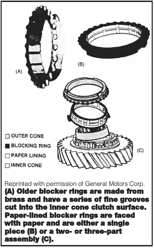
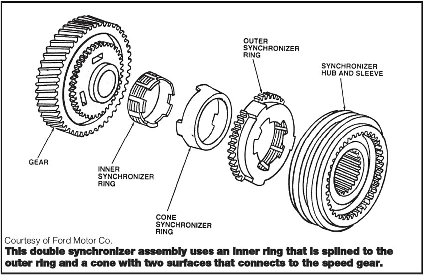
The synchronizer has a few working components, which include an inner hub that is splined on the inner bore to attach to the output or countershaft. A sliding sleeve is splined to fit onto the inner hub and has on its inner surfaces engagement teeth that will mesh with the speed gears on the main or countershaft. There are three or four synchronizer keys, which fit into slots on the hub and mesh with a groove on the inside of the sliding outer sleeve. The keys are held under tension by circular wire springs, or steel balls and coil springs. The keys always move forward or back with the sliding sleeve. Between the speed gears and the synchronizer assembly is the synchronizer (synchro) ring, which is a tapered cone-shaped ring that fits onto a tapered cone on the speed gear.
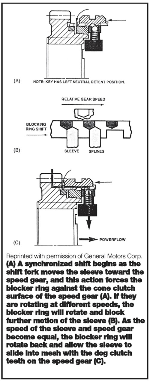
In operation, the driver depresses the clutch pedal, the clutch disengages and the input shaft stops turning. The driver selects a gear by moving the shift lever, and the shift fork then moves the appropriate sliding sleeve of a synchronizer assembly toward the speed gear selected.
As the sliding sleeve moves, it carries the synchronizer keys into contact with the synchro ring, which is a wet cone clutch that begins to engage the cone on the speed gear being selected. The synchronizer ring now has to speed up or slow down the speed gear being selected while at the same time blocking the sliding sleeve from contacting the engagement teeth on the speed gear until the speeds of the shaft and gear are equalized. Once the shaft and gear are turning at the same speed, the synchronizer ring will turn slightly, allowing the sleeve to contact the gear and complete the shift.
This sounds like a simple-enough operation, but wear and tear, abuse, parts failures and improper lubrication can make this into a problem that eventually brings the vehicle to your shop. The next step is for you to understand the operation of all the components involved so that you can repair it correctly the first time at a profit. Careful diagnosis will lead you to understand where to find the problem on teardown. Anything you don’t understand, or miss on the internal inspection, will create a comeback and a monetary loss.
Diagnosis by symptoms:
Hard shift – Heavy, steady pressure needs to be applied to the shifter to engage one or all gears.
Possible causes:
- Worn, damaged or misadjusted clutch creating loss of release
- Damaged or worn shift-mechanism components causing binding on internal or external shift linkage and components
- Improper transmission lubricant, which causes the synchronizer rings to slip or bind
- Worn synchronizer sleeve and hub causing binding or cocking of the sleeve on the hub.
Block-out (partial or complete) – Shift lever moves normally until a point where very high effort is needed to force completion of the shift, and there are conditions where the shift cannot be completed.
Possible causes:
- Improper lubricant that causes the synchronizer ring to be unable to slow or speed up the speed gear to match engine speed to driven-wheel speed
- Worn synchronizer ring or worn cone surface on speed gear
- Damaged internal components that block the fork or sliding sleeve from full movement to complete the shift.
Gear clash or grinding during the shift
Possible causes:
- Loss of clutch release
- Improper lubricant so that the oil viscosity makes it impossible for the synchro ring to change the speed of the speed gear selected
- Worn or broken synchronizer ring that cannot alter the gear speed and permits the sliding sleeve to contact the speed gear before speeds between the gear and shaft are equalized
- Worn taper on the cone of the speed gear that prevents the ring from affecting shaft and gear speed. Note: This condition usually will cause damage to the pointing on the engagement teeth of the speed gear and the sliding synchro sleeve. If the points are damaged, the gear and slider should be replaced to ensure smooth shifts. Failing to do so usually results in notchy shift feel.
Gear jump-out (hop-out) – After a shift is completed and the clutch is engaged, the unit will jump out of gear immediately, or slowly under changing throttle conditions.
Possible causes:
- Worn or broken powertrain mounts
- Misalignment of bellhousing or transmission
- Excessive endplay on the shafts or individual speed gears so that the speed gear can move out from under the sliding sleeve of the synchronizer
- Excessive runout of the sliding sleeve or speed gear
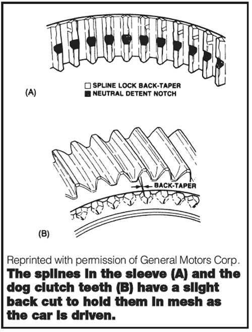
- Worn-out back taper on the sides of the engagement teeth on the speed gear or sliding sleeve
- Missing or worn crankshaft pilot bushing.
Locked in gear after a shift is completed
Possible causes:
- Damage or wear to shift rails or mechanism
- Overtravel of sliding sleeve due to endplay problems or worn synchro rings
- Overtravel of the sliding sleeve resulting in displacement of synchro keys, locking the sleeve in place.
Preventive measures during repair or rebuild:
- Before disassembling the unit, measure total shaft endplay in the transmission and then measure all speed gears for endplay.
- Check fit of hub to sliding sleeve for radial play, side-to-side rock and runout. Check splines for wear and for straightness.
- Check the engagement teeth on speed gear and sliding sleeve for damage to the pointing (gear clash) and wear to the back taper on the sides, which will cause gear jump-out.
- Check the fit of the synchro ring to the speed-gear cone. The ride height of the ring (synchronizer reserve) is important and should be measured against factory specifications but will not measure the wear on the taper of the speed-gear cone. To bulletproof the speed-gear cone, blue the cone with marking compound (layout blue) and twist a known good ring onto the cone. Remove the ring and observe the pattern left on the cone. The pattern should be uniform top to bottom on the cone with no skips. If you can’t get a good pattern, scrap the gear and sell the customer a new one. There is only one place to do it right the first time, because after you have agreed on a price with the customer you will pay for any parts you missed.
- Check the bores on all speed gears for wear and make sure there is no wear on the ends of the speed gears that will cause an endplay problem. Check shift rails and output shafts for bends and runout.
- Sell the customer new bearings on every job, and make sure all endplay tolerances are within specification.
Installation procedures:
- Check the clutch on every repair. You have already done all the hard work, and the worst thing that can happen is you will sell more clutches.
- Make sure to install a new pilot bearing and check for proper location and for damage to dowel pins in the engine block.
- Stone the mating surfaces of the block and bellhousing to make sure there is no misalignment caused by corrosion.
- Install an extra ground strap between the transmission and the engine block.
Make sure you use the correct factory lube fill on every unit. There are synchro rings made of brass, bronze, paper lined, carbon fiber, sintered metallic, and composite materials. There are single-cone, double-cone and triple-cone ring sets in late-model transmissions. A specific oil is specified for each of these transmissions, for both lubrication and proper synchro operation. Using the wrong lube will create a number of time-wasting headaches.
Do a thorough road test and verify shifting under hot and cold conditions, and require the customer to return the vehicle for a two-week checkup in order to maintain the warranty. Recheck the unit for leaks and road-test again on the two-week checkup. Pay particular attention to booted extension-housing seals that can get rolled when the driveshaft yoke is installed and not show signs of leakage because of the dust boot.
Understanding the theory, and planning and executing properly, will make a complicated job a lot easier.