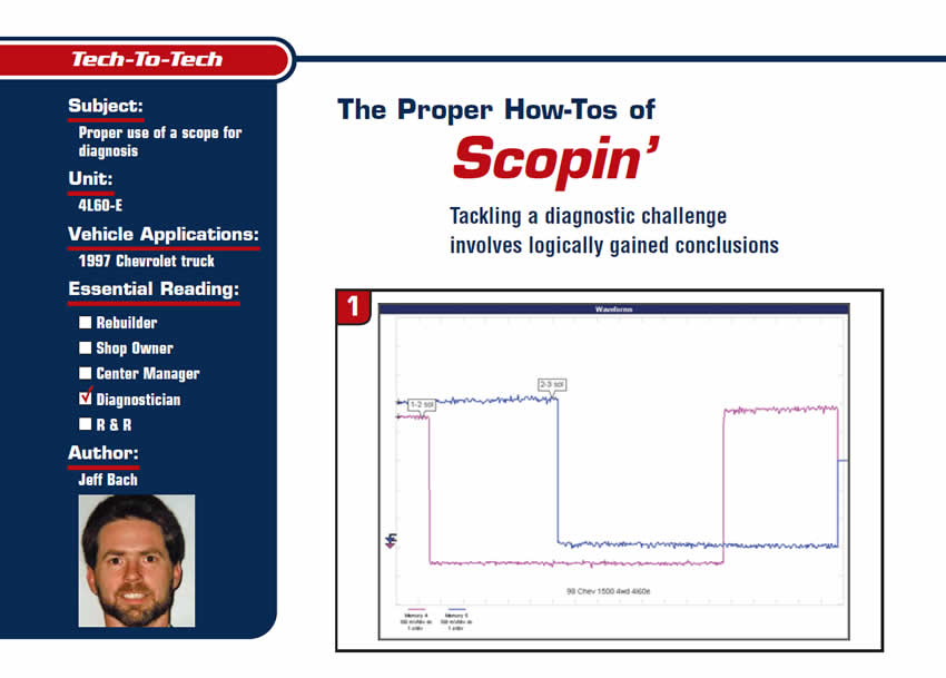
Tech to Tech
- Subject: Proper use of a scope for diagnosis
- Unit: 4L60-E
- Vehicle Application: 1997 Chevrolet truck
- Essential Reading: Diagnostician
- Author: Jeff Bach
Tackling a diagnostic challenge involves logically gained conclusions
I’m working on a 1997 Chevy truck that has an “intermittent transmission,” as the owner puts it. He goes on to explain, “It works fine most of the time but when it gets into its spell of acting up, it seems like all I get is one or two gears of bad gas mileage and no power.”
I’m assisted on this Chevy by my wife, Angel, who asks: “Now that I have the two circuits, I want to identify the waveforms. How do I set the scope to show me the images?”
The transmission has already been rebuilt. It had a new valve body put on it, along with the computer, trying to solve this problem. This transmission is electronically controlled using a combination of five solenoids and a pulse-width-modulated pressure control to operate four speeds and the torque-converter clutch.
I go over the technical details – referring to bulletins, recalls and known common problems, of which there appear to be many. It seems that this transmission has been plagued with a multitude of issues affecting the shift pattern, including – but not limited to – noisy rpm signals out of the distributor due to worn bushings, bad shift solenoids, worn valves in the valve body, throttle-position-sensor (TPS) signal noise, low voltage on the ignition circuit etc. I’m always amazed when I read the fix data on iATN. There are so many suggestions that seem confident enough, just from reading the description of the problem, to recommend the solution. I would even consider leaning toward looking into the solution if there were some commonalities or if an overwhelming majority said the same thing, but each technician seems to solve the problem with a different solution.
As a technician, how do you decide where to start looking for the problem after a review of the resources? Personally, I like to break the system into sections and work toward a solution using logically gained conclusions. I begin by setting up the scope to get the pictures I want of the shift-solenoid waveforms.
The scope screen is broken down into 10 gradicules called divisions. There is a “time” adjustment button that allows me to choose how much time I want to see in each division. “S” is for more time; “ns” is for less time.
We used a stopwatch to test-drive the vehicle to time the complete shift pattern. It takes between 15 and 20 seconds, depending on throttle pressure, to shift through all of the gears. This means that each division on the scope screen should be set to show 2 seconds to capture 20 seconds on a full screen or 2S/div. The scope can capture two screens at once. This means I can set the scope to 1S/div. Angel pushes the scope’s time button to achieve the desired setting.
Next, we need to adjust the voltage level on the scope to get it to show the solenoid current. The scope grid is divided into 10 sections going up to indicate the voltage level based on the volts per division setting. Normal solenoid current for this type of solenoid is going to be about a half of an amp or around 500 milliamps. The scope will best show the image at 100 mA (milliamps) per division. I used the same voltage setting for Channel B as we plan to look at each solenoid’s current by using two current probes. The scope has a single time base for both channels, so there will be no need to adjust it for the second channel.
Now that we have our scope set, I connected a current probe to the 1-2 shift solenoid at the powertrain control module (PCM) and hooked it to Channel A. Next, we put the other probe to the 2-3 solenoid and Channel B. The 1-2 shift solenoid is on when grounded by the PCM during first and fourth gears and off for second and third. The 2-3 shift solenoid is energized during the first and second gears and off for third and fourth (Figure 1).
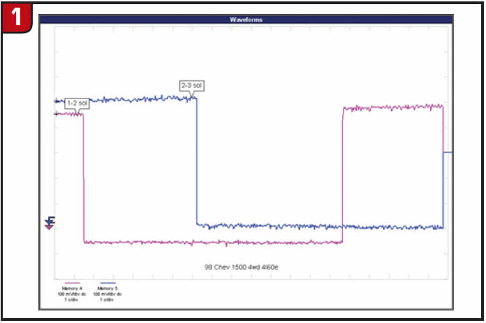
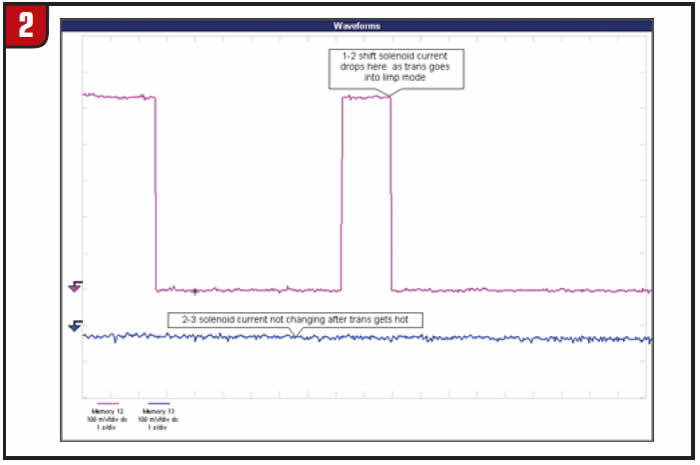
The first few starts were normal but as the transmission got up to temperature we lost the current on Channel B (2-3 shift solenoid). The next start after losing the circuit resulted in the PCM defaulting to limp mode (Figure 2).
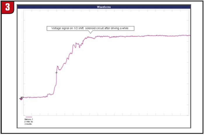
After the test drive, we got back to the shop and I reconnected Channel A to the actual control circuit for the 2-3 solenoid at the transmission connector using a piercing probe. I reset the scope to show a voltage level of 2 volts per division and sped up the time base to 2mS per division. Next, I triggered on the leading edge of the signal for Channel A. I road-tested the truck again over a bumpy road and got the waveform you see in Figure 3.
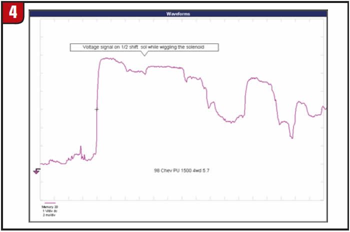
We verified the circuit at the trans connector to the PCM and determined that the problem was inside the transmission. Once the pan was removed, I could hook the probe directly to the lead for the 2-3 shift solenoid. With the PCM commanding the solenoid off, I still had a 0-volt reading on the control side with 12 volts on the feed. I wiggled the solenoid a bit and got the reading in Figure 4.
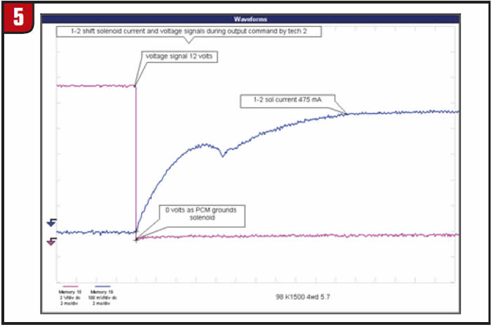
This confirmed that the problem was in the solenoid itself, and a new part was ordered. With the new part installed, we used the scan tool to command the solenoid on and off while monitoring the voltage and current with the scope (Figure 5).
We then gave the truck another extensive test drive over one of the most-scenic roads in the county. It shifted perfectly every time (Figure 6).
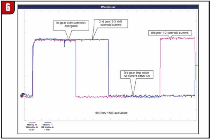
Now that you can see on the scope with two current probes how the PCM controls transmission shifts using the two shift solenoids, watch how it changes on the scope as I put both the control circuits through one current probe.
The problem with this hookup is that you can’t tell which solenoid is energized when only one is on – unless, of course, you cross the circuits going through the probe with, say, Channel B going through backward (Figure 7).
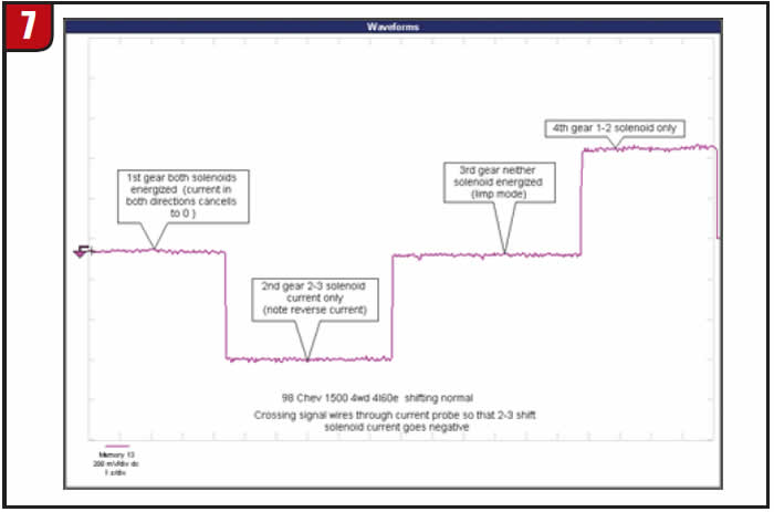
I’ve found this to be a very effective way to use one current probe to do the job of two, and it leaves the other scope channel open to look at a second signal.
Happy scopin’!

This copyrighted article is reprinted with the permission of AutoInc., the official publication of the Automotive Service Association (ASA). To learn more about ASA and its commitment to independent automotive-service and repair professionals, visit www.ASAshop.org or call 800-272-7467.
Jeff Bach is the owner of CRT Auto Electronics, an ASA-member shop in Batavia, Ohio. For more information on this topic, contact Bach at 515-732-3965. His e-mail address is [email protected].