RL4FO2A/RE4FO2A: Mysterious Axle-Seal Leak - Transmission Digest

RL4FO2A/RE4FO2A: Mysterious Axle-Seal Leak

A 1993 Nissan Maxima was brought to a transmission shop. The customer complained about a persistent transmission leak that was leaving a spot on his garage floor and said the transmission had been rebuilt about a year earlier. He added that the vehicle was returned to the original shop within the first month to have the passenger-side axle seal replaced. Since the axle-seal replacement did not eliminate the leak, the vehicle was taken to a general-repair shop, which replaced the axle seal and installed another axle under warranty. The customer said that each time the vehicle was worked on, the leak seemed to stop for about a month, then reappear.

RL4FO2A/RE4FO2A: Mysterious Axle-Seal Leak

TASC Force Tips

Subject: Cause of axle-seal leak in 1993 Nissan Maxima
Unit: RL4FO2A/RE4FO2A 
Essential Reading: Rebuilder, Diagnostician, R & R
Author: Ed Lee, Sonnax

TASC Force Tips

  • Subject: Cause of axle-seal leak in 1993 Nissan Maxima
  • Unit: RL4FO2A/RE4FO2A
  • Essential Reading: Rebuilder, Diagnostician, R & R
  • Author: Ed Lee, Sonnax

A 1993 Nissan Maxima was brought to a transmission shop. The customer complained about a persistent transmission leak that was leaving a spot on his garage floor and said the transmission had been rebuilt about a year earlier. He added that the vehicle was returned to the original shop within the first month to have the passenger-side axle seal replaced. Since the axle-seal replacement did not eliminate the leak, the vehicle was taken to a general-repair shop, which replaced the axle seal and installed another axle under warranty. The customer said that each time the vehicle was worked on, the leak seemed to stop for about a month, then reappear.

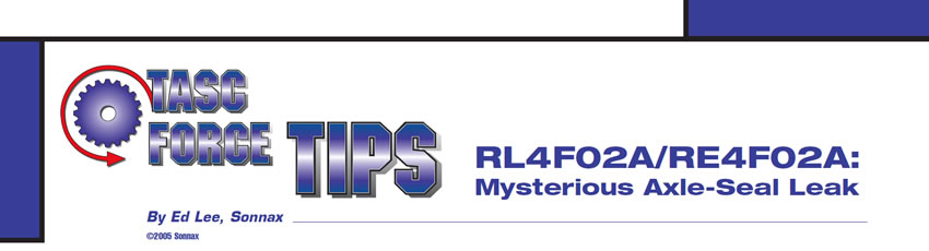
The technician who was working on the vehicle confirmed that the passenger-side axle seal and axle had been replaced recently and that ATF was dripping from the seal. The technician checked for side-to-side movement of the axle where it contacts the seal. His opinion was that play was present but not excessive. He also reasoned that the play was about the same as on the driver-side axle, which was not leaking. He pulled the axle out and removed the seal to inspect the differential carrier. The technician then exerted force on the carrier to make sure there was no play where the carrier was supported in the case. The carrier had no movement, and the inside diameter (ID) of the carrier where the axle passes through looked like new (see Figure 1).

Luckily, the pristine appearance of the ID of the carrier raised a red flag for the technician. He considered whether the shop that did the original overhaul had replaced the differential with an incorrect one – or one with an ID that was bigger than the OD of the axle. A check of the differential proved that it was the correct one for the vehicle and that the ID was the correct dimension. When the axle was measured where it contacts the differential, it was 0.070 inch smaller than the ID of the carrier. This led the technician to consider a second scenario: whether the axle had been replaced with an incorrect one, or at least with one that was smaller on the OD where it centered in the differential carrier. However, when the axle was checked out, it was the correct one for the vehicle and the OD dimension was correct for the axle.

That left the question of how the axle was being centered in the seal. The passenger-side axle on this transaxle is a two-piece unit. The inner section of the stub shaft is supported by a pillow-block bearing attached to the side of the engine. Unlike a one-piece axle, the stub shaft does not have a constant-velocity (CV) joint at the transmission end. The side gear into which the axle is splined is the only thing that centers the axle. The clearance between the side gear and the carrier must have been more than the seal could tolerate. But why didn’t the axle appear loose when the technician checked it? Therein lies a valuable lesson on checking for play at the axle.

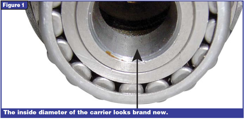
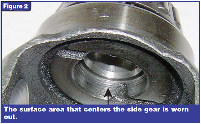
In one position, the spider gears that rotate on the cross shaft in the differential will support the side gear that drives the axle. If you pry on the axle on a plane that is parallel to the cross shaft, the axle will always appear tight. If you pry on the axle in any other position, the wear will show. The technician put the axle back into the differential and pushed it side to side on a plane that was perpendicular to the cross shaft. It had about 0.070 inch play (much more than the seal will tolerate). When the differential was removed from the transmission and taken apart, the wear was obvious (see Figure 2). At one time, one of the front wheels had been spinning faster than the other. You could tell this because of the galling on the cross shaft (see Figure 3). The vehicle probably either was stuck or was accelerated while on a lift.

Remember: Don’t be fooled by the pristine appearance of the differentials in RL4FO2A/RE4FO2A units, and be sure to check them by prying on the side gears perpendicular to the cross shaft.

Ed Lee is a Sonnax technical specialist and a member of the TASC Force (Technical Automotive Specialties Committee), a group of recognized industry technical specialists, transmission rebuilders and Sonnax Industries Inc. technicians. ©2006 Sonnax

You May Also Like

Sherlock Holmes Approach to an AB60 No-Move Situation

The effectiveness in diagnosing automatic transmission malfunctions is an art form. Although there are similarities among the wide varieties of transmissions on the road, each transmission has its own peculiarities. Aside from having mechanical, hydraulic, and electrical hardware systems to contend with, software/programming issues and various vehicle platforms make diagnostics much more difficult.  Using scopes provides

ab60

The effectiveness in diagnosing automatic transmission malfunctions is an art form. Although there are similarities among the wide varieties of transmissions on the road, each transmission has its own peculiarities. Aside from having mechanical, hydraulic, and electrical hardware systems to contend with, software/programming issues and various vehicle platforms make diagnostics much more difficult. 

GM 6T40 Pump Identification Guide

The 6T40 was introduced in 2008 for General Motors front-wheel-drive cars in the Chevrolet Malibu and has gone through several changes throughout its three generations, specifically in the pump area. The 6T40 is closely related to the more lightweight 6T30 and the heavier duty 6T45 and 6T50. Generation one started phasing out during the 2012

Seeing the Forest AND the Trees

They say that the proverbial phrase “I couldn’t see the forest for the trees” means that a person or organization cannot see the big picture because it focuses too much on the details. Related Articles – 4L60E Harsh 1-2 Shift – TASC Force Tips: Diagnosing 8L45 & 8L90 Shift Complaints – TASC Force Tips: Hydraulics

The Manifold Pipeway

The Honda six-speed transmission has been on the bench of many specialty shops for one reason or another (figure 1). But, for those of you who have yet to lay your hands on one, mounted on the upper side of the unit is one of the largest, if not the largest solenoid and pressure switch

8L90 Vacuum Testing

Below are the diagrams for vacuum testing GM 8L90 transmissions. Note: OE valves are shown in rest position and should be tested in rest position unless otherwise indicated. Test locations are pointed to with an arrow. Springs are not shown for visual clarity. A low vacuum reading indicates wear. For specific vacuum test information, refer

Other Posts

Shift of the shaft: Diagnosing Chrysler 48RE manual shaft issues

The TorqueFlite transmission has been around since mid-to-late 1950s. There have been many changes surrounding the manual shaft and rooster comb through the years. This transmission shaft controls the position of the manual valve that directs oil for the gear ranges, but it also is used for a Reverse light control as well as Park/Neutral

Diagnosing Ford 10R60, 10R80 and 10R140 series speed sensor issues

Ford 10-speed 10R series transmissions utilize four two-wire, Hall-effect sensors — TSS, ISSA, ISSB and OSS — for providing speed signals to PCM or TCM. They are supplied nine volts by a PCM or TCM and assist in the control of clutch apply/release timing that is used in determining shift quality, including TCC. Related Articles

Easy TH400, 4L80-E reverse servo setup: Craft your own tool

While not as sensitive as some shifting bands, the Reverse band adjustment on a TH400 or 4L80-E transmission is critical, and failure to get it right has tripped up even the best builders. There is nothing worse than getting the transmission installed, putting it in Reverse and then not going anywhere or having no engine

Understanding lube flow control valves in Toyota/Lexus UA/UB80 transmissions

The Toyota/Lexus UA80 and UB80 transmissions first came out in 2017 in Highlanders and Siennas. The UA80 is used in V6 applications, and the UB80 is paired with four-cylinder versions. They have been called Toyota New Global Architecture type transmissions, and alternately referred to as the “Direct Shift 8AT” eight-speed automatic transmission. This transmission was

Tasc-Tip-December-Figure-1---LFC-Valve-OE-Partial-Circuit-Diagram-1400