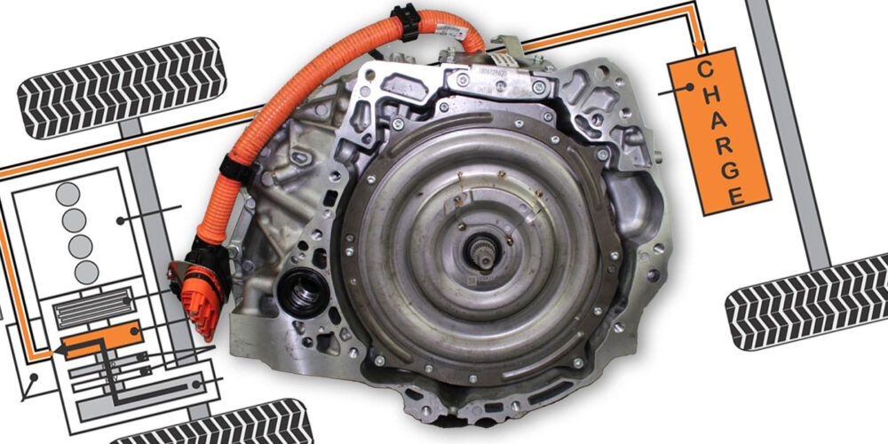
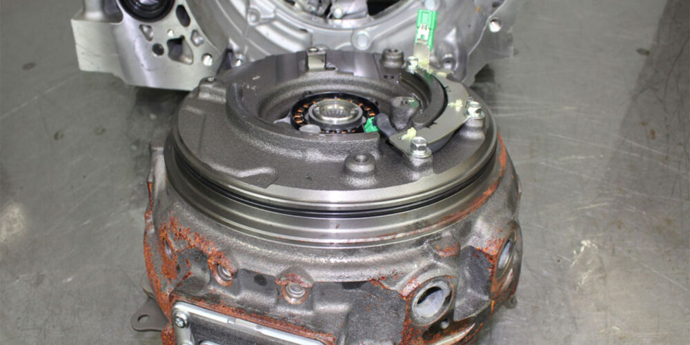
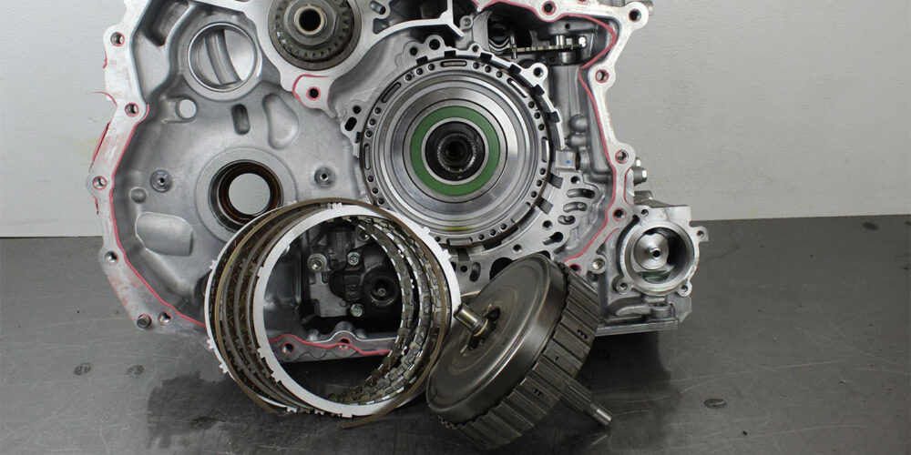
Nissan’s Hybrid RE0F02/3H CVT transmission by Jatco (JF019E) can be found in vehicles such as the Nissan Rogue and Pathfinder as well as the Infiniti QX60. It has its traction motor located where the torque converter would normally be (as you can see in Figures 1, at the top of the page, and 2, below).
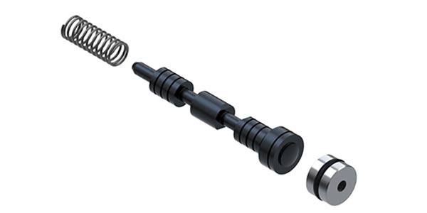
The transmission itself is similar to the company’s RE0F10D/E CVT 8 design. In fact, the valve body looks identical. The difference is that the lockup solenoid is called a Clutch 1 solenoid (see Figure 3).
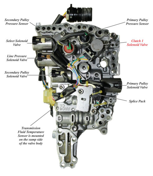
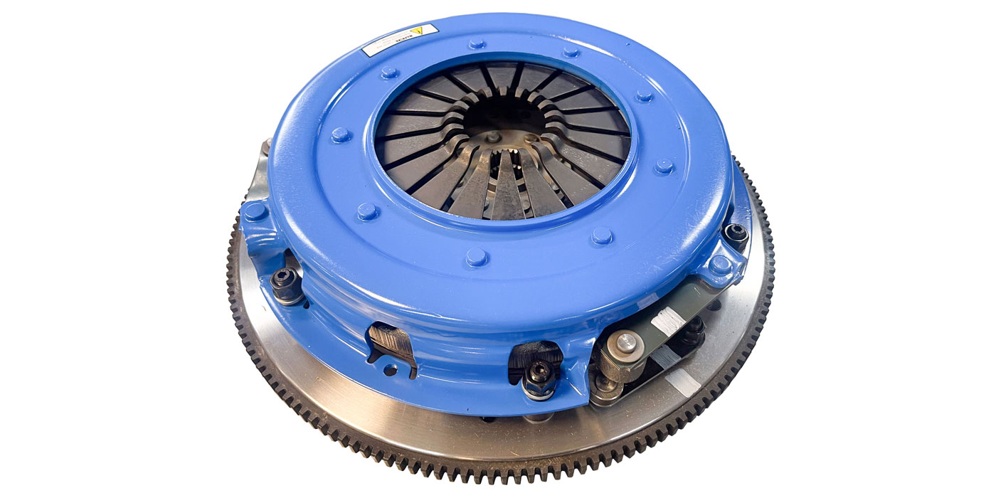
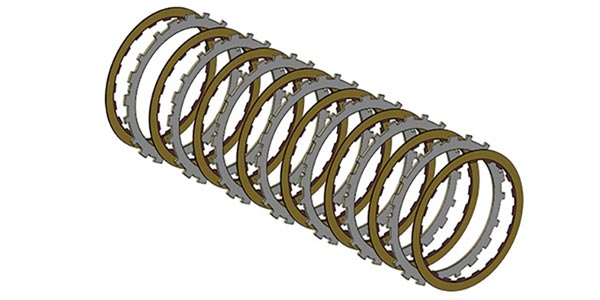
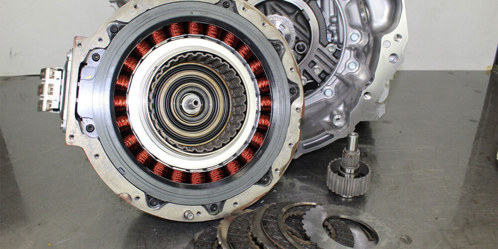
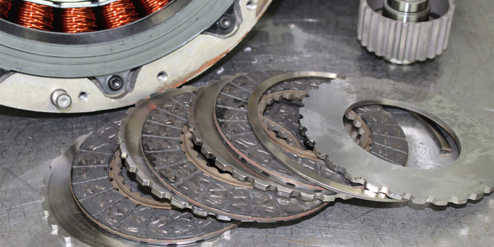
Like a lockup solenoid, this solenoid controls the apply and release of Clutch 1, which is a multi-plate dry clutch assembly positioned inside the front of traction motor (Figures 4 and 5).
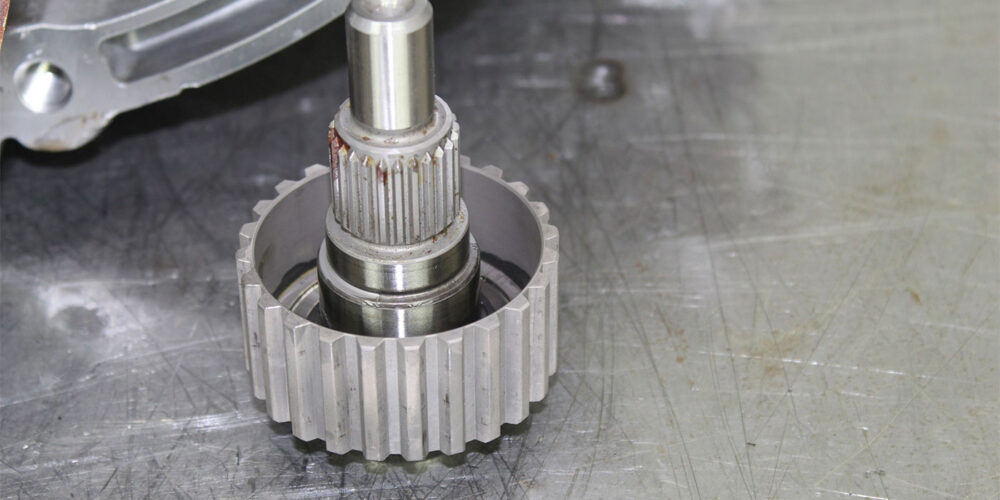
The hub for Clutch 1 is splined to a shaft that is driven by a torsional drive plate bolted to the crank (Figure 6). Inside the transmission is a reverse brake and forward drive clutch assembly, which is referred as Clutch 2 (Figure 7).
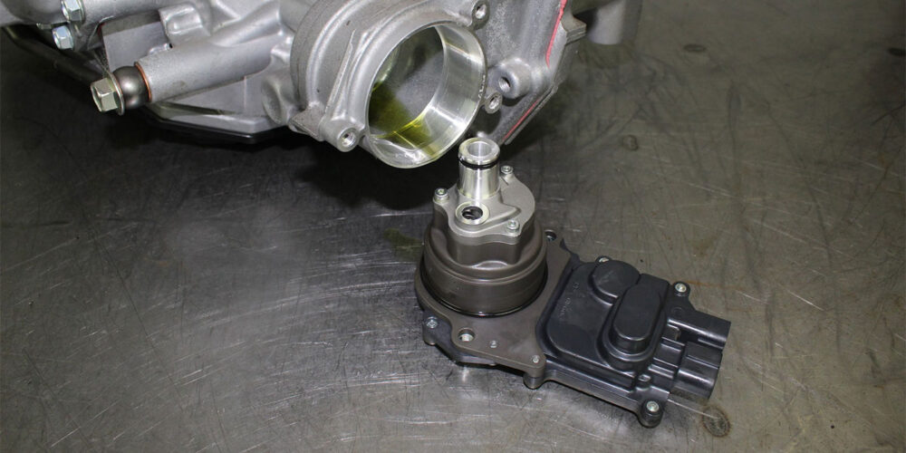
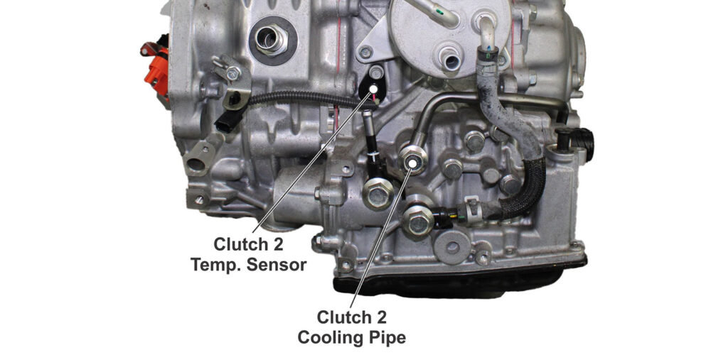
Under certain driving conditions, Clutch 2 will be commanded to slip, requiring additional cooling to prevent these assemblies from burning. To accommodate this requirement, an electrical cooling pump is mounted to the transmission close to the sump, as seen in Figure 8.
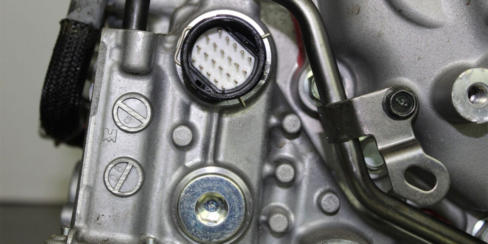
This pump draws fluid from the sump and routes it through a pipe that runs past the solenoid pass through case connector (Figure 9) and is mounted just below the heat exchanger as seen in Figure 10. There is also a temperature sensor located in the general vicinity, which is used as an input to let the computer know when to activate the cooler motor.
With the traction motor being positioned between the engine and transmission, power can be supplied to the transmission by either the traction motor or the engine. The input shaft to the transmission can be rotated by either of these two power supplies. The input shaft also turns the pump’s drive gear to provide hydraulic pressure to the transmission.
In the rear of the vehicle there is a lithium-ion battery which is controlled by the Hybrid Powertrain Control Module (HPCM) through an inverter (see Figure 11).
This HPCM can provide commands to the inverter to use the traction motor or engine to supply power to the transmission, or to charge the Li-ion batteries.
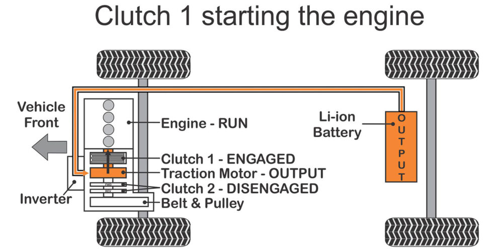
To start the engine, the HPCM commands the traction motor to rotate. This, in turn, produces hydraulic pressure in the transmission. The Clutch 1 solenoid turns on to engage Clutch 1. This rotates the engine, allowing for it to start. The vehicle is equipped with a conventional starter motor to start the engine under specific conditions; for instance, in extremely low temperatures.
The HPCM will also start the engine using Clutch 1 when the engine hood is detected as open. It will also start when the selector lever is in the park position, the driver’s seat belt is unbuckled and the driver’s side door is open.
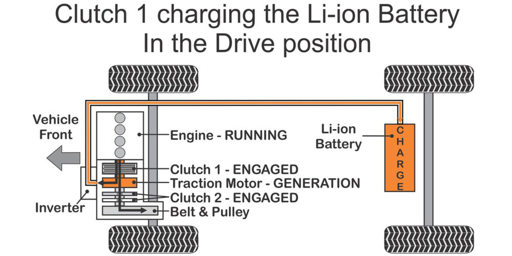
When the Li-ion battery is low, with the gas engine running, Clutch 1 can then be used to drive the Traction Motor, which in turn can charge the Li-ion battery while in Park (see Figure 12), or when being driven (see Figure 13).

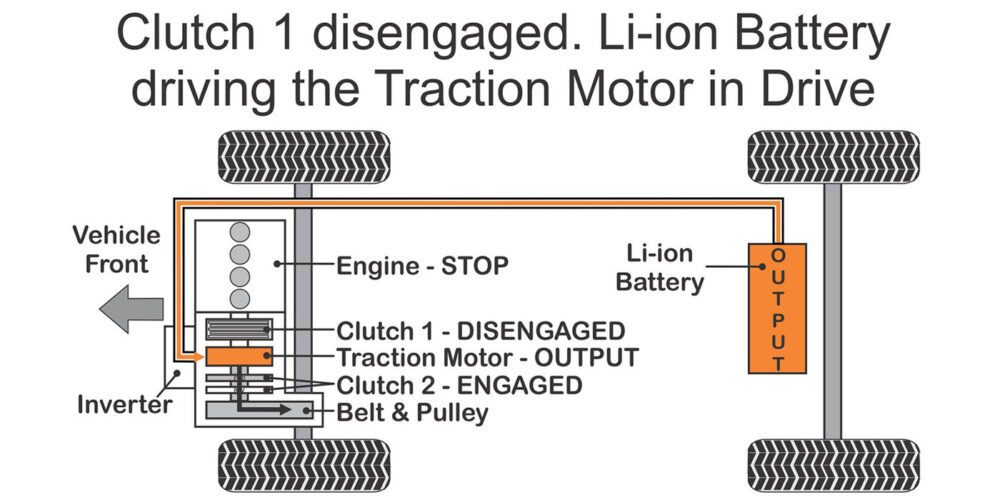
When the Li-ion battery is charged to the point that it can provide power to the traction motor to drive the vehicle, the gas engine shuts off and Clutch 1 disengages (see Figure 14).
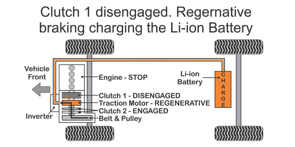
When the vehicle is in deceleration, Clutch 1 and the gas engine will remain off. Regenerative braking will then use the motive power of the wheels to generate power from the traction motor to charge the Li-ion battery (Figure 15).
These examples of how Clutch 1 is used in this hybrid CVT transmission provide a general idea of how active this multi-plate drive clutch is, and why this makes it prone to failure.
In part 2 of this article, coming soon, we will demonstrate a series of example as to how Clutch 2 is used, along with seeing these components and what controls them.
Read more stories from our Technically Speaking column series here.