

Allison, way back in the early ’90s, developed a new transmission platform to replace the older MT (medium-duty) and HT (heavy-duty) transmission lines. The new “World Class” line of transmissions was completely different from previous models in overall design. In addition, the MD (medium-duty) and HD (heavy-duty) applications have full electronic control. It came as no
surprise that when GM needed a beefy transmission to accommodate their pickup line, Allison was chosen as the supplier.
Initially, when the LCT1000 (light commercial truck) transmission was launched in 2000, it was utilized by Chevy only and components had to be purchased from Chevy dealers. As time went on, though, the line was expanded to other non-GM commercial vehicles. Today, the transmission line is merely referred to as 1000, 2000 or 2400, and components can be purchased through Chevy or Allison dealers depending on application. Certain items may only be available from one company or the other, while other items are available from both.
As with other transmissions over the years, the 1000 series has had numerous design changes to not only address deficiencies, but also to provide functional changes and enhancements to address customer demands. Not only has the internal iron changed almost yearly, electrical components as well as computer strategy have also
seen a fair amount of upgrades.
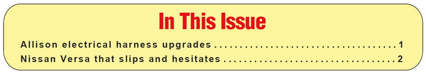
The first 1000 transmission that Chevy used was a five-speed automatic with a six-solenoid valve body, which also contained a PSM (pressure-switch manifold). The A and B solenoids were called trim solenoids, the C, D & E were shift solenoids and the F solenoid was for TCC. Initially, the electrical harness was fairly basic and used a traditional-looking gray 20-way GM case connector (Figure 1).
The original OE part number was 29541116; however, there was an issue with terminal fit, so that part number was superseded by 29541371. One way to identify the new design is by the two updated red solenoid terminals, and it is recommended that the new version is used.
Early on, the 1000 series had a noise issue concerning the pump that caused Allison to address. This was due to the fact that line pressure was regulated at a fixed amount, including at engine idle; therefore, the vehicle owner could hear the pump whine even in park or neutral. Beyond the steps taken to upgrade the pump assembly, Allison decided to also make changes with the electrical system.
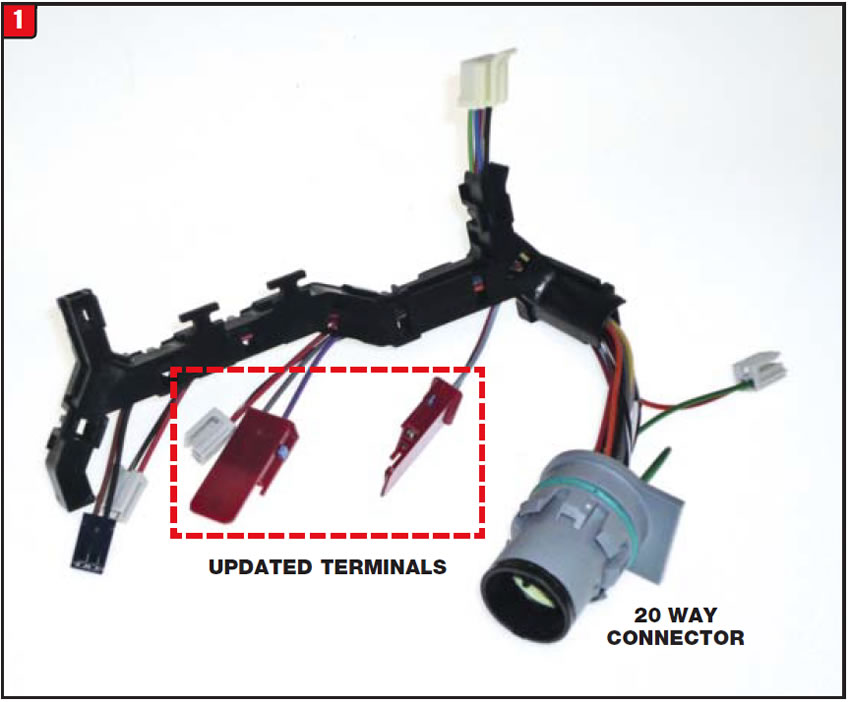
By mid-2003 Allison added a small auxiliary valve body and solenoid (now seven in total) to the main body. The upgrade was referred to as the main modulation control assembly and G solenoid, which of course affected the electrical harness assembly by adding additional wires (Figure 2). The previous harness design actually has the same quantity of wires as the newer part, but the additional wires are just cut short, no pigtail. The purpose of adding the new G solenoid was to reduce line pressure under certain conditions, thus minimizing the load on the pump and eliminating the noise. With the exception of the additional terminal, the new harness looks identical to the previous design, and the OE part number is 29539792.
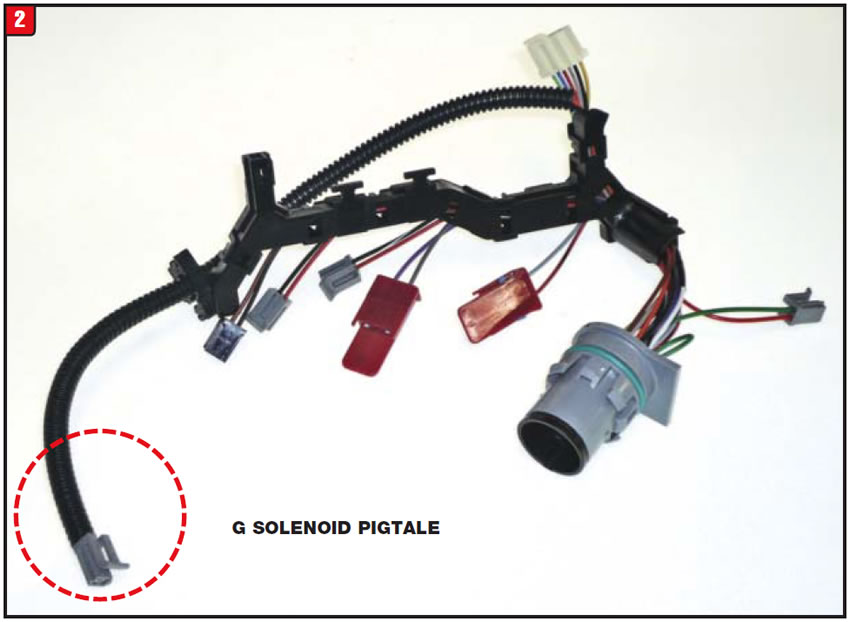
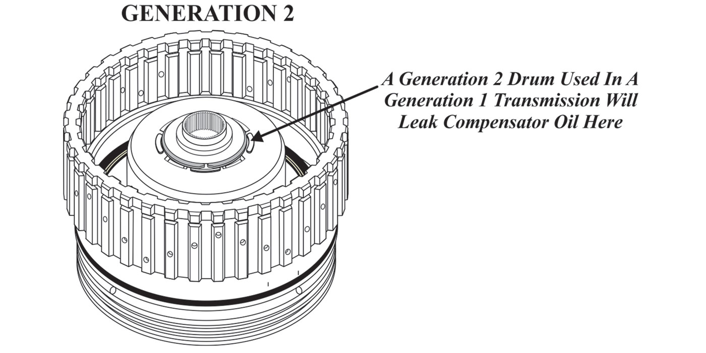
By 2006 big changes were occurring to 4 the 1000 series of transmissions, both internal and external, which Allison refers to as GEN 4. Some of these changes started to be phased in during the 2005 model year depending on application, but all were implemented by the beginning of 2006. Concerning electrical components, the changes were noticeable. For instance, the external NSBU (neutral-start backup) switch was replaced by an IMS (internal-mode switch) and of course the harness assembly was affected due to adding a terminal that coincidentally looks like the PSM wire terminal (Figure 3).
A key change that occurred to the 2006 models was the addition of a sixth gear over the previous five speeds. To accommodate the new gear several changes were made to the valve body and certain solenoids. The previous A & B trim solenoids were replaced by a VBS (variable-bleed solenoid) design. In addition, the TCC solenoid was changed to a similar design resulting in new terminals for all three positions. 5 GM applications continued to use the gray 20-way case connector. The GM electrical harness part number is 29543336.
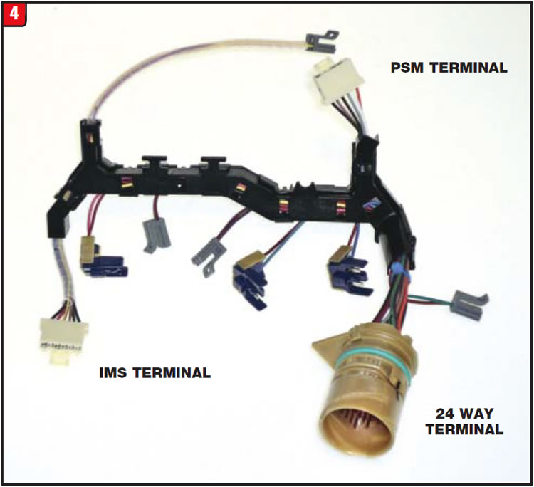
On the commercial side of the fence, Allison followed suit somewhat with overall computer strategy and solenoid configuration. For some reason Allison chose not to use the same case connector that had been used by GM. The case connector for non-GM commercial applications is a 24-way design (Figure 4). Solenoid layout and part numbers are common between both groups, although the wiring is different due to the case connector. This model of case connector only uses 21 wires with pin cavities 5, 12 and 13 being empty. The commercial harness part number is 29543334 and is beige in color.
The changes that occurred in 2006 pale in comparison to what happened with 2010 transmission models relating to just about every widget in the units. There is very little interchangeability between early and late designs, although the transmissions are still six speeds. Although the valve body changed substantially, most solenoid part numbers did remain the same with the layout being somewhat altered.
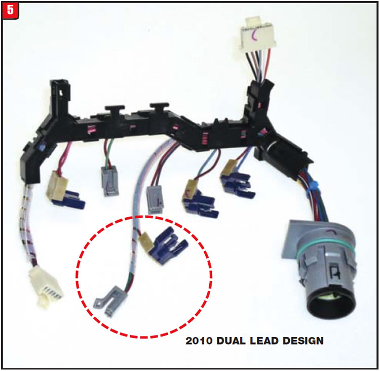
Previously, the approach to line-pressure control went from a steady line pressure (2000-03) to merely reducing line pressure at times (2004-09). Allison finally decided in 2010 to control line pressure like most other automatic transmissions by adding a variable modulated main solenoid and eliminating the G solenoid, still ending up with seven solenoids. The electrical harness had to be modified, yet again to accommodate the change (Figure 5). As illustrated, the G pigtail is gone and there are now two terminals on one lead. As with other harnesses for GM applications, the case connector is the gray 20-way design. The OE part number is 29545307.
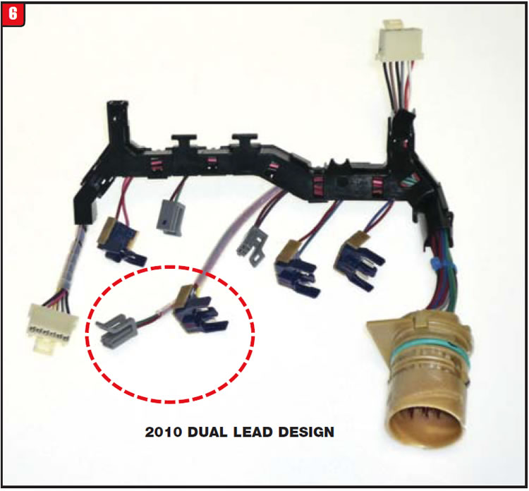
As with previous commercial applications, the 2010 models coincide pretty much with the GM transmission changes. There are of course some differences between GM and commercial application software relating to certain modes of operation. That is why Allison chose to continue with the beige 24-way case connector for later models. The 2010 commercial harness also has 21 wires, leaving three empty pin cavities, numbers 5, 12 and 13 (Figure 6). The part number for this application is 29545308.
Beginning with January 2013 production, Allison has implemented transmissions with 5th-generation control features. In an effort to enhance fuel economy and promote cooling, two computer strategies are available for specific models, both of which achieve similar goals by providing a form of neutral at stop. One system is referred to as RELS (reduced engine load at stop) while the other system is referred to as ECLR (enhanced converter load release).
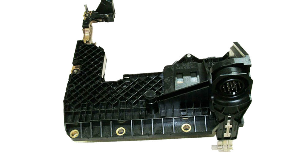
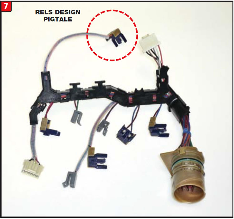
In order for these systems to work, the valve body had to be modified again using a flash from the past. An auxiliary body was just added to the main valve body in a similar fashion to when the auxiliary body and G solenoid were added in 2004. This time, however, the total number of solenoids has increased to eight, as did the number of terminals on the harness assembly (Figure 7). Currently, only the beige 24-way commercial case connector is used with only the number 5-pin cavity being empty. The part number for the harness assembly is 29554091.
It remains to be seen how many more mutations might occur in the future, but for the present there are certainly enough to choose from.


The owner of a 2012 Nissan Versa Sedan started to experience some odd behavior from the vehicle that was recently purchased as a used car from a private seller. Although the vehicle had 63,000 miles on it, the current owner’s portion was low, only about 4,000 miles. In addition, the current owner was not that familiar with the particular way that the vehicle should operate. Although it was hard for the car owner to distinguish, there was actually more than one problem that he was experiencing. At times, when he would step on the gas, there was a hesitation that was more engine related than transmission related. While at other times the issue was actually a transmission engagement problem. Beyond that, the transmission would slip while driving down the road under certain conditions.
The reason that the owner of the vehicle, and for that matter most other people, had a problem trying to discern what was going on was due to the transmission design. The Versa in question came equipped with a 1.6L engine and a CVT transmission. This CVT, however, is not just an ordinary continuously variable transmission, but rather one that actually upshifts and downshifts like any other step type transmission (Figure 8).
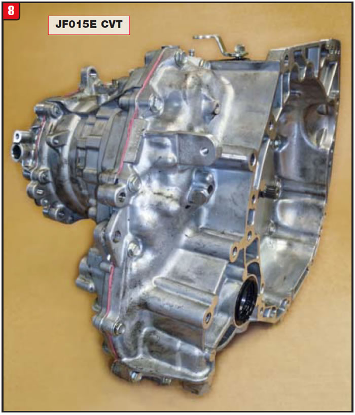
The Nissan name for the unit is RE0F11A while the Jatco handle is JF015E or CVT-7. The challenge became which assembly was causing the variety of issues, the engine or transmission or both. In addition to problems that can be caused by the engine or transmission is another feature that this particular vehicle has, which is a neutral-at-stop option. Sorting out the good from bad was going to be no small chore.

Although there was no check engine light, the vehicle was driven several times with a scanner hooked up to have a sense of what was going on and to check for any possible trouble codes stored in the system. None were found, so diagnosis was based upon operation. To avoid chasing ghosts, a search was performed for any TSBs and there were several relating to this vehicle and specifically to these issues.
For instance, bulletin number NTB 15-069 concerns a transmission slipping condition that occurs under certain conditions. Another TSB, bulletin number NTB13-100B, relates to an engine stall or hesitation problem. Yet another TSB, bulletin number NTB15-082, also describes an engine hesitation issue due to a bad taillight circuit board. First things first, as they say, so the focus started with the engine hesitation problem.
After reviewing the details within all of the bulletins, a common thread started to surface, which was the need to reprogram not only the ECM, but also the TCM. Therefore, to avoid any needless wrenching, it was decided to let the reprogramming begin.

Unfortunately, reprogramming the computers on this vehicle was no one-stop shopping, as each procedure had to be done separately, although both procedures are similar. Following is a snapshot view of the Nissan approach:
Most instructions for reprogramming with CONSULT-III plus (C-III plus) are displayed on the CONSULT PC screen.
Connect the GR8 to the vehicle battery and set to Power Supply Mode. The vehicle battery voltage must stay between 12.0V and 15.5V during reprogramming, or the ECM may be damaged.
Connect the CONSULT PC to the vehicle to begin the reprogramming procedure. Start C-III plus. Wait for the plus VI to be recognized. The serial number will display when the plus VI is recognized.
Select Re/programming, Configuration. Follow the C-III plus on-screen instructions and navigate to the screen shown in Figure 2. When you get to the screen shown in Figure 2, confirm this bulletin applies as follows.
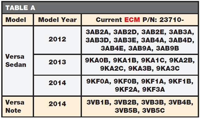
Find the ECM part number and write it on the repair order. Compare the P/N you wrote down to the numbers in the current ECM part number column in Table A below to confirm a match. Continue with the reprogramming procedure. Follow the on-screen instructions to navigate C-III plus and reprogram the ECM. When the screen in Figure 4 displays, reprogramming is complete.
Select Next. In the next step you will perform DTC erase. DTC erase is required before C-III plus will provide the final reprogramming confirmation report. Follow the on-screen instructions to Erase DTCs.
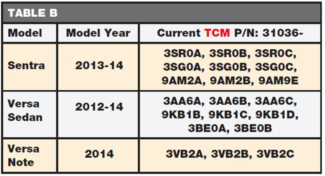
When the entire reprogramming process is complete, the screen in Figure 7 will display. Transmission programming is done in a similar manner to engine programming. Use the following TCM Table B to verify the vehicle TCM part number. Reprogramming of the ECM will address the engine-related issues while the TCM redo will help with transmission pressure problems.
Miraculously, once the ECM reprogramming was done, the initial engine hesitation was gone and engine performance seemed pretty good overall along with the correct neutral at idle feature. The other issue, however, was not affected, which was a slipping condition while driving down the road.
Under certain conditions such as automatic or manual upshifting, the transmission would flare or slip to a certain degree. The cause of this was mainly due to an internal pressure problem that not only involves transmission components, but computer strategy as well.
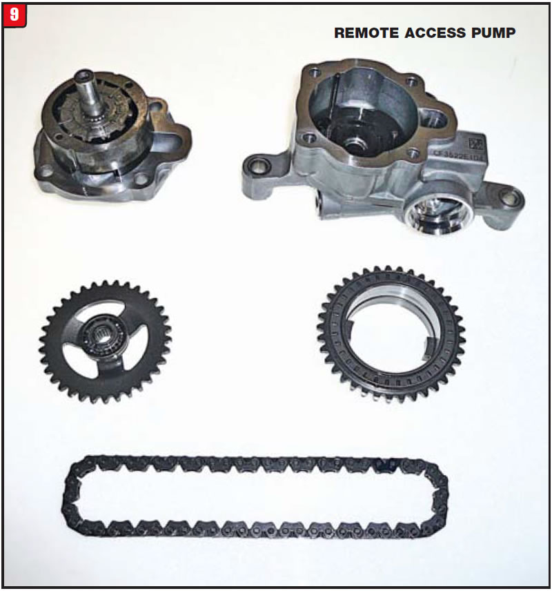
Unlike a regular step type transmission, a CVT requires a substantial amount of line pressure, in the range of 600 to 800 PSI. The JF015E actually has a chain-driven remote access pump instead of a direct drive pump, unlike some other CVT units (Figure 9).
Other transmission manufacturers have started to use the remote-access pump design in a variety of transmissions in order to address fuel economy and performance concerns. It takes less engine juice to turn this design due to the gear ratio advantage.
All CVTs use a push belt or drive chain between two variators (pulleys); however, the JF015E belt/pulley design was made to accommodate smaller vehicles and engines with limited space (Figure 10). Due to the auxiliary gear-box, as it’s referred to, the diameters of both pulleys were reduced not only to limit space, but also to prevent fluid agitation.
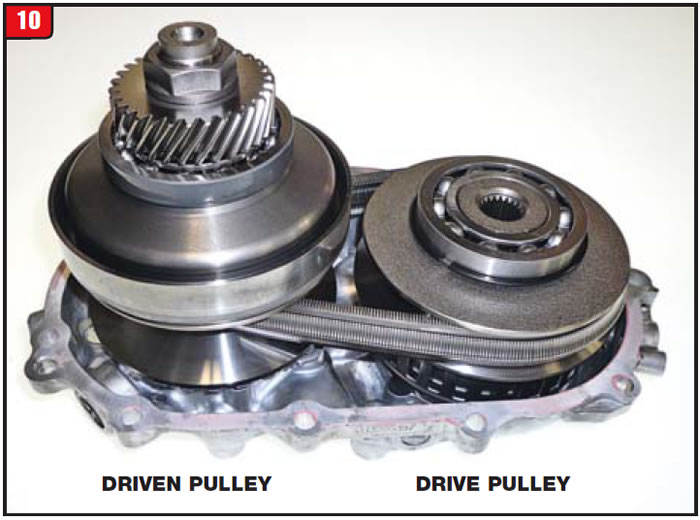
Unlike other CVTs, both pulleys are rebuildable, but use caution not to bend the sensor rings.
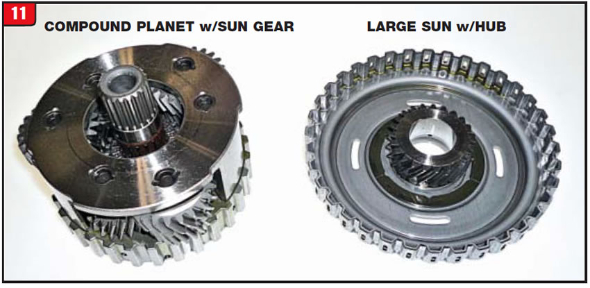
A regular CVT changes ratio only by moving the drive and driven pulleys from an open to closed position and back. There is one simple planetary set that is connected by one clutch assembly for forward and one brake assembly for reverse. The JF015E auxiliary gearbox provides a low and high range in addition to the changing pulley ratios, which provides an overall ratio with a wider spread. The main gear-box component responsible for the stepped shift is a planetary, which is the compound design utilizing two sun gears (Figure 11). The large sun gear has a clutch hub welded to it.
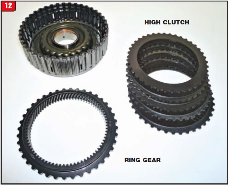
One of the friction elements that is common to other CVTs is the high clutch assembly, although in all other CVTs the clutch is referred to as the forward clutch, because there is no shifting. The high clutch assembly is a normal looking clutch drum with frictions and steels, but also has a ring gear that splines to the drum (Figure 12). Clutch operation is just like any other unit.
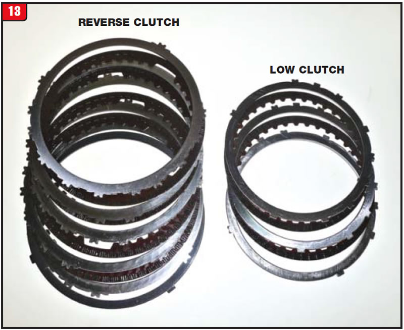
Unlike other CVTs that only use one stationary brake assembly for reverse, the JF015E not only has a stationary brake for reverse, but also has a stationary brake for low (Figure 13). The reverse brake is the larger of the two and when applied holds the high clutch drum/ring gear stationary. The low brake assembly splines to the large sun gear clutch hub and when applied holds the sun gear stationary for low gear.
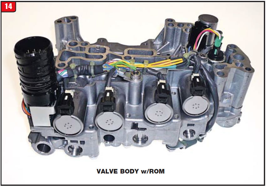
Previous model CVT valve bodies were somewhat unique due to having an array of different solenoids, but mainly for having a ratio-control motor. Later model CVTs such as the JF015E no longer use a ratio-control motor that makes things a little easier; however, there are still several items to deal with (Figure 14). There is one component on the valve body that most other transmissions do not have and that is a ROM unit. The ROM is not to be confused with a mechatronic (TEHCM) design that uses an internal TCM. The Nissan Versa has an external TCM that communicates with the ROM assembly.
Once both the ECM and TCM were reprogrammed, the vehicle ran great without any sign of hesitation or slippage. A normal service was performed on the transmission and the customer was sent happily on his way. It just goes to show a little computer tweaking can go a long way. Apparently, Nissan is having some noticeable issues with certain vehicles that come equipped with a CVT since they have extended the powertrain warranty to 10 years or 120,000 miles, whichever comes first. It would be advisable to check with Nissan before doing any repairs.


May 2016 Issue
Volume 33, No. 5
- Allison electrical harness upgrades
- Nissan Versa that slips and hesitates