
Shift Pointers
- Subject: Using a wiring diagram to help diagnose an electrical problem
- Unit: 722.5
- Vehicle Application: 1995 Mercedes S320
- Essential Reading: Diagnostician
- Authors: Jesse Zacarias & Roy Delfran
If we understand how something works, then we stand a better chance of repairing it should it fail. That may seem like a logical statement, but it is not always easy figuring out how a transmission is designed to work electrically, and many times the right information is not easily available.
We have found the wiring diagrams of a transmission to be a very useful tool in figuring out how it is designed to work electrically. This information can help narrow down the problem when we are dealing with an electrical malfunction.
For example, a customer came in with a 1995 Mercedes S320 with a 722.5 automatic transmission, complaining of no fifth gear, ABS light on and no speedometer reading. According to the customer this happened from one day to the other. He had already had two mechanics try to repair the problem, but they were unable to do much because their scan tools would not communicate with some of the modules, a problem we also encountered. What adds to this problem is that you cannot back-probe the modules because of the way they are installed in the vehicle, and most of the electrical devices are either sealed or in a very difficult place to get to.
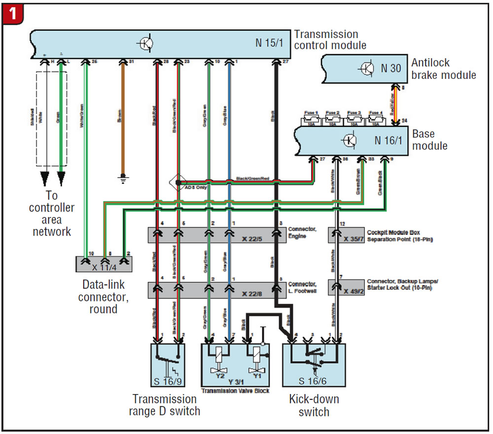
The logical thing to consider was the speedometer, but how does it operate? The wiring diagrams showed that the ABS module (N 30) uses the input from the right-front wheel-speed sensor to calculate the vehicle speed and then sends this information to the rest of the modules via the controller area network (CAN) and to the instrument panel.
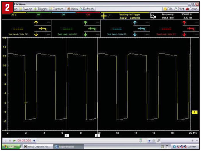
The electronic control for fifth gear is not very complicated, either (see Figure 1 for the following explanation). The wiring diagram shows that the transmission control module (N 15/1) modulates the Y2 valve in the valve body. It actually does this at 300 Hz and at about 66% duty cycle when the transmission is in first through fourth gears (Figure 2).
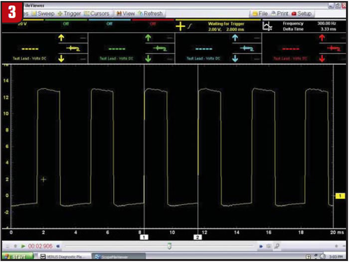
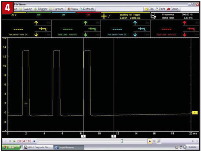
If the TCM receives a voltage signal (switch close) from the transmission-range D contact switch (S 16/9) requesting fifth gear at pin 28, then at the proper speed and throttle opening the TCM will stop modulating the Y2 valve. It does so gradually, changing the modulation on time until it is fully off (figures 3 and 4).
The base module (N 16/1) provides the voltage for many of the electrical devices of the vehicle, but we concentrated only on the transmission-range D contact switch, the TCM and also to the ABS module.
The base module can have up to four external fuses (this one has only two) for protection. The fuses are named F1, F2, F3 and F4 (Figure 5). We found that these fuses were not shown in any of the aftermarket wiring diagrams that we looked at, only in the factory wiring diagrams.
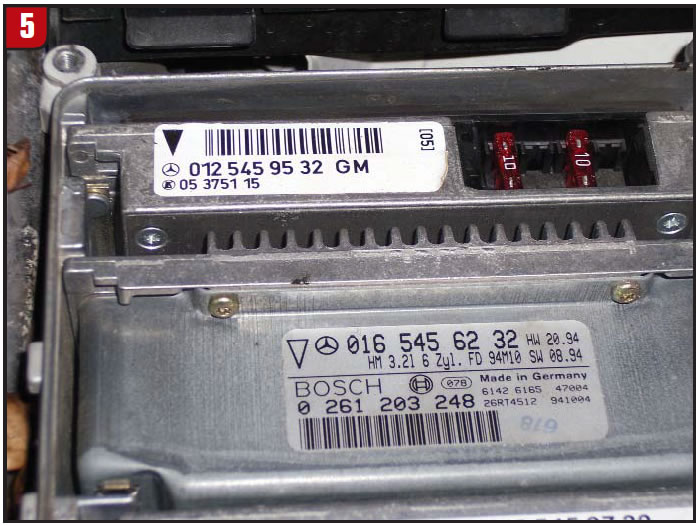
Failure of any of these four fuses can cause the base module not to provide voltage to the transmission-range D contact switch, kickdown switch S 16/6, TCM and ABS module.
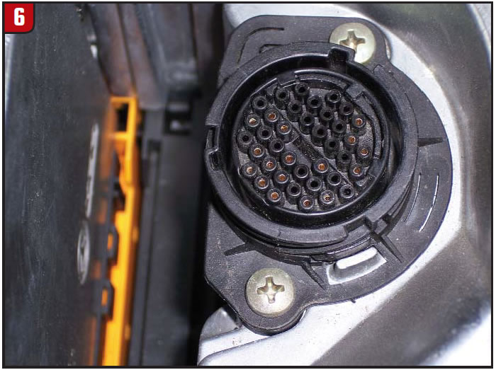
The base module also provides voltage to pins 2 and 8 of the round data-link connector (X 11/4). Most scan tools make use of this voltage, which is the reason we were not able to communicate with some modules.
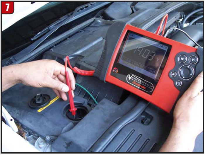
The best way to verify the integrity of the fuses is by checking for voltage at pins 2 and 8 of the 32-pin data-link-connector socket with the engine running; you should see battery voltage (figures 6 and 7).
In this particular case, the F1 fuse was blown, affecting the circuit to the ABS module, which in turn did not allow the vehicle-speed signal to be sent to the TCM. Therefore, the Y2 valve never stopped modulating and the instrument panel showed 0 mph all the time. After spending some time to find a reason for the blown fuse, possibly a short, we asked the customer what had been done to the vehicle prior to the problem. He informed us that his battery had drained so he had the vehicle jump-started – a simple thing but with dire consequences, which reminds us of the importance of disconnecting the battery when charging it.
Remember, taking the time to analyze the wiring diagrams can help us to better approach electrical problems.

Jesse Zacarias is the owner of Elec-Tran Diagnostics in Gilroy, Calif. Roy Delfran is with Snap-on Diagnostics “Ask-a-Tech Web Services” (http://askatech.snapon.com).


