Up to Standards
- Author: Mike Weinberg, Contributing Editor
You can’t read or discuss anything about automobiles without getting into performance figures and estimates.
The manufacturer creates a specific plan for the performance of the car it is bringing to market, basing the plan on vehicle cost, weight, engine size, torque capacity of the engine and a set of gear ratios to provide the best performance and drivability possible. Tire size, aerodynamic drag and parasitic friction losses are all studied to get the most-fuel-efficient platform with enough acceleration to make the vehicle safe in passing conditions. As the budget for the vehicle increases, the performance levels increase in general, and some models offer options of several different engine, transmission and final-drive ratios.
We as rebuilders need to understand some of the mathematics used to arrive at these designs, because we will be asked to change some vehicle components to upgrade or change performance, and there will be times when we have to correct or exchange something previously done by the customer or a previous owner. In other cases the manufacturer will cease to produce certain ratios of transmissions, and it will be necessary to replace a transmission with a ratio that is lower numerically and change the final-drive ratios to compensate.
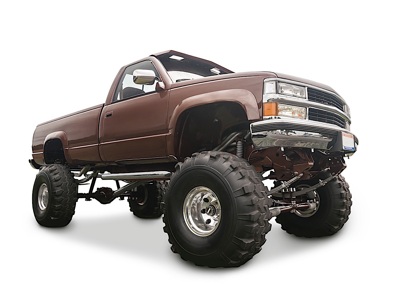
Customers routinely “dress up” their vehicles with larger wheels and tires – without any thought to the consequences – and then ask a repair shop to “make the speedometer right” or other calibration changes. In the performance and enthusiast market, which generates billions of dollars in sales, ratio changes to transmissions and final drives are an everyday request.
Regardless of your position in the industry you will need to understand some basic math to help you solve these problems. Everything that follows will involve simple arithmetic that does not require higher education to use and can be done with simple multiplication, division, addition and subtraction.
Ratios are the relationship between sets of gears that are in mesh and measure the distance covered by revolution of the smaller gear in comparison with the larger gear. For example, if the smaller gear has 10 teeth and the larger gear has 30 teeth, the small gear will have to make three revolutions for the larger gear to complete one revolution. This would give you a 3-1 ratio.
Since a transmission’s purpose is to transmit power, the ratios designed into it are to make the engine’s horsepower and torque usable. Understand that low gears have numerically high ratios and that high gears have numerically low ratios. A numerically higher ratio means that the gear set can provide more pulling power at low engine speed and the engine will reach its maximum speed at a lower road speed.
If it takes 150 horsepower to break a vehicle away from a dead stop, the same vehicle will use 15 horsepower on flat ground to maintain 60 mph. The designers have to develop a set of transmission ratios that make the car fuel efficient and able to do the work it was designed for – hauling either passengers or cargo.
The torque curve of the engine now comes into play. Engines typically begin to produce torque at 1,000 rpm, and the amount of torque will increase until about the middle of the speed range and then begin to drop off. For instance, a typical stock small-block Chevy engine will start making usable torque at 1,000-1,200 rpm and reach maximum torque of 381 lb.-ft. at 3,500 rpm, and the torque level will drop off to about 285 lb.-ft. at 5,500 rpm. Obviously, there is a wide range of engines with torque curves to match, which is why there is such a variety of transmission ratios.
Another thing to consider in advertised torque and horsepower ratings is where they are measured. Most advertised ratings are obtained from measurements that are calculated (informed guesstimates) or are measured on an engine dynamometer at the crankshaft. The only true measurement that counts is horsepower and torque obtained at the drive wheels. This will always be less than crankshaft horsepower because of parasitic losses through the driveline. The essence of good design is to make the most usable torque at the drive wheels in each gear of the transmission.
Calculating ratios is simple. To do so one must know the tooth counts of each set of gears and the tooth counts of the final-drive gears. The math always entails dividing the input tooth count into the output tooth count.
This means that if you are calculating the main drive-gear or input ratio, you would divide the number of teeth on the input gear into the number of teeth on the output or driven gear with which it meshes on the countershaft. When you wish to find the ratio of a speed gear on the main shaft, you must divide the number of teeth on the countershaft gear (input) into the number of teeth on the opposing main-shaft gear.
The first ratio you must obtain is the INPUT ratio. This is determined by dividing the number of teeth on the input journal of the countershaft by the number of teeth on the input or main drive gear and will be used to calculate all the gear ratios in the transmission.
Example: We have a four-speed transmission with a main drive or input gear that has 19 teeth. We have a countershaft or cluster gear with tooth counts of 29, 24, 20 and 18. The main-shaft speed gears have the following tooth counts: 3rd speed, 21; 2nd gear, 25; and 1st gear, 34.
- Input ratio: 29 divided by 19=1.52, which we will multiply by each speed-gear ratio to determine the actual ratio in each gear.
- 3rd gear: 21 divided by 24=0.87, which we multiply by the main-drive ratio, 1.52, to obtain our 3rd-gear ratio, 1.32.
- 2nd gear: 25 divided by 20=1.25. 1.25 X 1.52 (main drive ratio)=1.90, which is our 2nd-gear ratio.
- 1st gear: 34 divided by 18=1.88. 1.88 X 1.52=2.85, which is our 1st-gear ratio.
Now we know that the transmission has the following ratios:
- 1st gear, 2.85-1;
- 2nd gear, 1.90;
- 3rd gear, 1.32; and
- 4th gear, 1-1 (direct drive).
Next we need to know the final-drive or differential ratio. You arrive at that the same way, by dividing the number of teeth on the pinion (input) into the number of teeth on the ring gear (output). Let’s say, for example, that we have an 8.5-inch Chevy differential with a 41-tooth ring gear and a 10-tooth pinion. 41 divided by 10=4.10, which is our final-drive ratio. We then can calculate the overall ratio in each gear by multiplying our transmission ratios by the final-drive ratio:
- 1st gear, 2.85 X 4.10=11.68 overall ratio in 1st gear
- 2nd gear, 1.90 X 4.10=7.79 overall ratio in 2nd gear
- 3rd gear, 1.32 X 4.10=5.41 overall ratio in 3rd gear
- 4th gear, 1.00 X 4.10=4.10 overall ratio in 4th gear.
Just for fun, let’s say we had a six-speed transmission in which 5th and 6th were overdrive gears and the vehicle had a 4.10 final-drive ratio. 5th gear is 0.80-1 and 6th gear is 0.62-1. The overall ratio in these two gears would be:
- 5th gear, 0.80 X 4.10=3.28
- 6th gear, 0.62 X 4.10=2.54
You can see a huge difference between the overall ratios in 1st through 6th gears. What this means is that in 1st gear the crankshaft will turn 11.68 times for each revolution of the drive wheels and in 6th gear the crankshaft will turn 2.54 times for each revolution of the drive wheels. This is a comparison of the mechanical advantage obtained in the lower (higher-ratio) gears with the fuel economy and lower engine speed obtained in the higher (lower-ratio) gears.
Ratio calculations are also useful to get you out of some nasty jams when using exchange or junkyard units. Many times the exchange or junkyard unit will not have the same speedometer drive gear as the unit you have taken out. Sometimes it is possible to just swap gears from old unit to replacement, but you can use calculations of speedometer-gear ratios to find the correct driven gear for the application.
Example: The original unit had a seven-tooth drive gear and a 21-tooth driven gear. Your customer has a replacement unit with an eight-tooth drive gear. Divide 7 (the number of teeth on the original drive gear) by 8 (teeth on the replacement gear) and you get a ratio of 0.875. Now divide the number of teeth on the old driven gear (21) by the ratio of 0.875 and you will get 24. A 24-tooth driven gear will make the unit work correctly.
In most instances a good calculator will give you two and sometimes three decimal places, such as 0.87 or 0.875. In many of your calculations you will wind up with fractional answers such as 23.33. Rounding off the numbers to the nearest digit, 23.33 will become 23, and 23.78 will become 24. This will be close enough for what you are trying to accomplish with gear-driven transmissions and speedometers.
Advanced math for other calculations is necessary to solve some problems for your customers. Advanced is just another way of saying we will use the calculator more. Once you know the formulas, it is all simple arithmetic, no more difficult than balancing your checkbook and a lot easier than programming a VCR. From time to time you will be asked to change a differential ratio for a customer because he is looking for better fuel mileage or better low-speed acceleration off the line. Other problems will arise when a customer “blings” up his car with taller tires and wheels. The following formulas will help you to calculate the differences caused by the changes:
Mph = rpm X tire diameter divided by gear ratio X 336. When you wish to be accurate about tire diameter, remember that the loaded tire on the vehicle is no longer round. To get correct tire-diameter measurements, measure the drive wheel from the centerline of the axle to the ground and multiply the result by 2. This will give you a corrected figure that takes into account the deflection of the tire’s contact patch on the ground.
Engine rpm=mph x gear ratio x 336 divided by tire diameter. Using these formulas correctly will help you know in advance the changes in vehicle and engine speeds that will occur as a result of ratio and tire-size changes and will allow you to predict or correct conditions.
We hear a lot about wide- and close-ratio transmissions. Understanding the difference between the two has a lot to do with vehicle performance and drivability. Consider that the difference between gears in a transmission can be compared with the height of steps on a staircase. It is easy to walk up stairs in which the risers are 8 inches tall and obviously more difficult to climb a flight of stairs with 12-inch risers.
Wide ratios are generally desirable for vehicles that need more mechanical advantage and have the engine speed to work with greater differences, or steps, between gears. Diesel engines typically have a narrow power band in which they make useable torque, usually 1,200-3,000 rpm. This explains why many over-the-road and heavy-duty trucks have 10- to 16-speed transmissions. The “steps” between gears before the engine reaches the rev limit are narrow, so there must be more of them to keep the engine working in the correct power band.
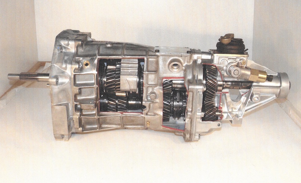
High performance also has specific needs in gearing to keep the engine in the optimum range for maximum speed and torque. For example, a T56 six-speed in a Z06 Corvette will have the following ratios:
- 2.97-1, 1st
- 2.07-1, 2nd
- 1.43-1, 3rd
- 1-1, 4th
- 0.80-1, 5th (overdrive)
- 0.62-1, 6th (overdrive).
These are pretty reasonable ratios for street driving and drag racing. In fact, these ratios were added to the Z06 to get the 0-60 times down around 6 seconds for advertising and bragging rights. The steps between these ratios will cause a drop of about 1,500 rpm during a shift.
Now, if you wanted to use this transmission in a road race, it would cost you elapsed time on the stopwatch. If we use a T56 with road-race ratios – which are 2.29-1, 1st; 1.61-1, 2nd; 1.22-1, 3rd; 1-1, 4th; 0.85-1, 5th (overdrive); and 0.75-1, 6th (overdrive) – we can see that in this close-ratio transmission the steps between gears are much narrower and result in a loss of about 750 rpm for each shift.
The application for this transmission is different from the one used in the street car, because with most road races having a rolling start 1st gear is not important, and the vehicle is constantly being driven as close to full throttle as possible. The same thing happens in oval-track racing between short tracks like Richmond or Dover and super speedways like Daytona and Talladega. The NASCAR teams will change differential ratios to keep the engine in its best power band. At a short track they may have to use a 6.75-1 differential ratio to keep the engine turning between 8,000 and 11,000 rpm. On a 2.5-mile super speedway, they will use a much lower (numerically) differential gear to increase top speed and keep engine speed high.
To understand the problems facing the engineers when they design a vehicle, we need to look at some more math. Nobody just pulls transmission and differential ratios out of a hat.
They must calculate the load the drivetrain works against in everyday use of the vehicle. The formula is simple, but collecting the data needed is complex.
The engineers will look at tractive resistance, determined by the formula TR = Fr X Da X Gr.
- Fr = rolling friction, which is the drag of the tires on the pavement plus parasitic losses due to bearing and gear friction. Rolling friction increases at a constant rate and will double as road speed doubles.
- Da = aerodynamic drag, which is the friction and resistance of the vehicle body moving through a fluid (air). This drag will increase at a rate of velocity squared, which means a four-fold increase in drag as speed doubles.
- Gr =grade resistance, which is the amount of effort increased by changes in road grade. It is measured at 0.01 times the vehicle weight multiplied by the angle of the percentage of grade.
All these factors reflect on the design criteria for a vehicle. In real-world terms everything is a compromise balancing cost, performance, drivability, fuel economy, emissions standards, crashworthiness and styling. It is difficult, if not impossible, to create a design for general use by the public that will please everybody. The auto manufacturers do a wonderful job of producing products that fit the budgets and tastes of the motoring public and work really well for their intended use.
Real race vehicles are not drivable on the streets. Vehicles capable of extremely high fuel economy will sacrifice power and speed. Vehicles with heavy suspensions that can carry heavy loads will not handle and ride as comfortably as a passenger car. You should now be mathematically prepared to work with the variety of vehicles and customers that make up our industry.


