
Up to Standards
- Subject: Operation and troubleshooting of Magna Powertrain transfer cases
- Units: MP3023 and 3024
- Essential Reading: Rebuilder, Diagnostician
- Author: Mike Weinberg, Rockland Standard Gear, Contributing Editor
Operational theory and diagnostics
This is the last of a three-part series on the Magna Powertrain MP 3023 and 3024 transfer cases. These are electronically controlled “active” transfer cases (ATC).
The RPO code for these units is NQH. Each of them has two operating ranges and five drive modes: Auto 4WD, 4High, 4Low, 2High and neutral. These vehicles should be driven in the Auto 4WD range on hard pavement. This mode makes use of a computer-controlled internal wet-clutch pack to send torque to the axle that needs it on demand with no driver input.
These units are tuned to the specific vehicle in which they are used through calibrations in the software for the transfer-case control module (TCCM) and have adaptive logic. Part of the programming includes flexible adapt ready positions and regulation of clutch-preload torque levels. Modulation of clutch application is dependent on vehicle speed; for instance, the clutch applies a 5-lb.-ft. preload at 0-24 mph, and torque application in line with the vehicle speed and engine torque at 25 mph or faster. This low-speed preload gets rid of the crow hop and binding common in 4WD vehicles during low-speed driving.
A dash-mounted Transfer Case Control Switch allows the driver to select any of the five transfer-case modes. The switch is live anytime the ignition is in the run position. When the driver selects a mode, the light on that mode will begin to flash and continue to do so until the shift is complete. At that point the switch position will maintain a steady light until the driver commands a new shift mode.
When the transfer case is operating in the Automatic 4WD position power is sent to the rear axle. The wheel-speed sensors monitor all four wheels, and when a slip condition is detected the control module sends a pulse-width-modulated (PWM) signal to the electronic actuator motor, which then applies the clutch by rotating the actuator shaft, applying the clutch to levels determined by the computer software and sending torque to the front axle. As the wheels speeds equalize the clutch application returns to the 2WD calibration until a slip occurs again.
The position of the actuator control shaft is monitored by the incremental sensor. This switch converts the actuator-shaft position (which mode or range) into an electrical signal to the TCCM with a specific voltage level for each position, which is returned on the incremental-encoder impulse circuit and converts into which range or mode the actuator shaft is in.
The transfer 2/4WD actuator is mounted on the transfer case and moves the actuator arm clockwise or counterclockwise through two motor circuits, A and B. There is a driver on each circuit, and the actuator motor shifts through the different modes and ranges and applies the clutch through a PWM signal in response to input from the TCCM. This motor is a permanent-magnet DC unit with a planetary-gear reduction system, making it capable of applying hundreds of pound-feet of torque to the clutch pack.
The actuator motor is equipped with a motor lock that engages in each of the modes to hold the transfer case in the selected mode. Energizing the lock circuit permits the motor to turn. Once the desired shift position is reached the motor-lock circuit goes back to zero voltage, locking the motor in the selected position. In the auto 4WD mode the circuit will energize in response to a slip input from the computer, permitting the clutch to be applied. When the shaft speeds equalize the circuit will return to zero voltage. There is also a transfer-case actuator-position sensor that works in conjunction with the incremental sensor to show transfer-case position by degrees.
The TCCM is programmed to select vehicle-specific information from multiple internal programs through inputting of the VIN into the computer. This allows the manufacturer to have one TCCM for many variations of axle ratio, tire size, and engine and transmission configuration. When replacing the TCCM you must use a scan tool to input the VIN so that the module can select the appropriate software. The TCCM monitors the rotating speeds of the front and rear output shafts to detect wheel slippage and activate the clutch.
There is also a vehicle-speed sensor (VSS) mounted on the transfer case that measures the speed of the rear output shaft and sends that reading to the powertrain control module (PCM). It is a PM generator providing an AC voltage signal that increases with shaft speed. The PCM communicates this information to the TCCM through the GM LAN serial data bus. Again it is easy to see how mismatched or worn tires will create a diagnostic problem.
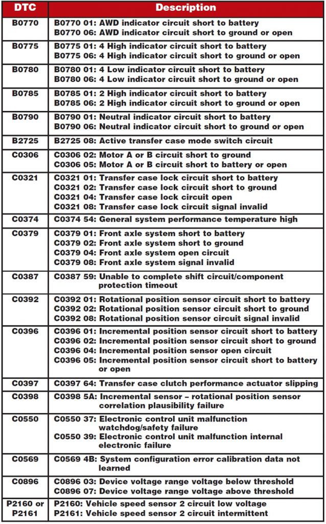
Current models of the TCCM are able to set 19 different trouble codes, which are illustrated on the accompanying chart. A word to the wise here: If you wish to save time – and time is money – you will need access to a quality information system on the vehicle. I have found the Mitchell OnDemand system to be the best outside of the GM factory program. It has excellent wiring and circuit diagrams and good diagnostic procedures.
You will need a good scan tool with the proper late-model GM modules. Hooking up the scan tool will let you begin your diagnosis with the Diagnostic System Check-Vehicle. This will now permit you to identify the right procedure for diagnosing the vehicle and give you the location of the procedure.
By now it should be obvious that Thomas Edison and Albert Einstein could not diagnose these vehicles without the proper scan tools and manuals. These are interactive controls that will permit you to operate the motors and equipment through the scan tool. Before starting any scan, make sure the engine is running at idle, normal operating temperature is achieved, the throttle is closed, the transmission is in park or neutral and all accessories are off. There are at least 32 transfer-case parameters that can be accessed through the scan tool.
We have been living for a long time in an age in which you can no longer be successful in repairing a vehicle without access to the electronic controls and information. A successful repair will always start from the outside in. MEASURE tire sizes and air pressures. Use the proper scan tools to locate the DTCs. Repair the DTC and correct any other faults external to the transfer case. This does not mean that there will be no internal damage to the unit, but if you pull the unit out without establishing all external faults, you will lose the only dyno you have, which is the vehicle, and you will waste huge amounts of time and money. The manual on the internal repair is one-third smaller than the diagnostics and electrical section.