Up to Standards
- Subject: Design and operation of new Magna Powertrain transfer cases
- Unit: MP3023/3024 NQH
- Essential Reading: Shop Owner, Center Manager, Rebuilder, Diagnostician, R & R
- Author: Mike Weinberg, Rockland Standard Gear, Contributing Editor
In last month’s article we discussed two of the three new models of transfer cases from Magna Powertrain, the MP1222/1225/1226 NQG and the MP1625/1626 NQF. This month we will discuss the operation and mechanical functions unique to the MP3023/3024 NQH. Figure 1 breaks down the identification code for the MP3023. These are active transfer cases (ATC) with sophisticated advanced electronics.
Next month we’ll study the electronic diagnosis of the MP3023/3024 NQH, as that will fill an article by itself.
It is important for you to realize that when in the automatic-4WD (A4WD) position an active transfer case has the ability to monitor feedback from the wheel-speed sensors; traction-control, antilock-braking and stability-control systems; and other inputs such as yaw and steering angle, and to engage the internal clutches to send power to the front axle as needed to split torque to stop wheel spin. This is all done without any driver control.
In this series of transfer cases the transfer-case control module applies 0-5 lb.-ft. of clutch application at road speeds under 25 mph and much higher torque levels at speeds above 35 mph. This negates wheel hop and binding at low speeds and permits greater torque biasing at higher speeds to maintain vehicle stability. The internal clutch application in the A4WD position is controlled by the transfer-case shift-control module (TCSCM), which sends a pulse-width-modulated signal in response to input from the wheel-speed sensors. The actuator motor turns a gear-driven actuator shaft, moving a clutch-application cam to engage the clutch and send torque to the front axle. When the front and rear axle speeds match, the actuator motor returns to the 5% duty cycle.
Shift positions
The MP 3023/3024 transfer cases have five shift positions on a dash-mounted dial.
- A4WD is the active-clutch-application mode and may be used on dry pavement at all times. The other 4WD positions are not for use on dry pavement.
- 2WD High has no clutch engagement, with all power to the rear axle.
- 4WD High has full clutch application and is locked to provide a 50/50 torque split front to rear. Use this only in snow, mud or loose-soil conditions.
- 4WD Low has full clutch application and is locked, providing a 50/50 torque split front to rear with a 2.68-1 gear reduction through the planetary gearing. It is for off-road use only.
- Neutral permits the vehicle to be towed without moving the transmission output shaft. The rear prop shaft continues to drive the transfer-case oil pump, providing pressurized lube.
The neutral position can be achieved only if the ignition switch is in the run position, the transfer case is in the 2-high mode, the transmission is in park or reverse, and road speed is less than 3 mph.

Model variations
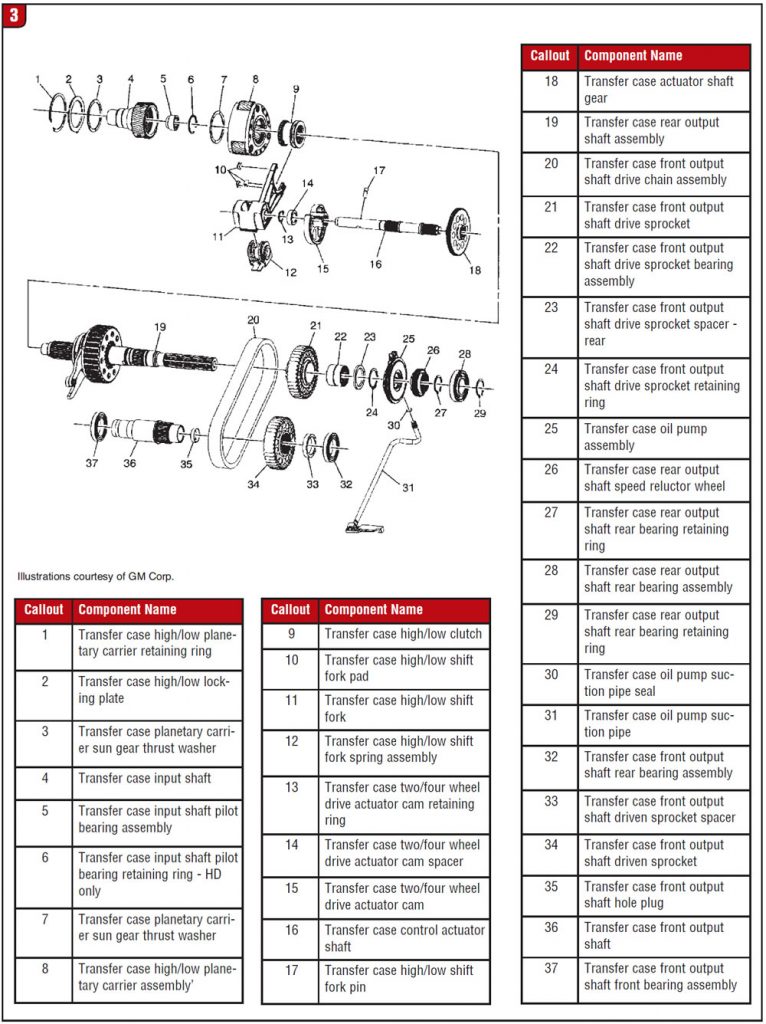
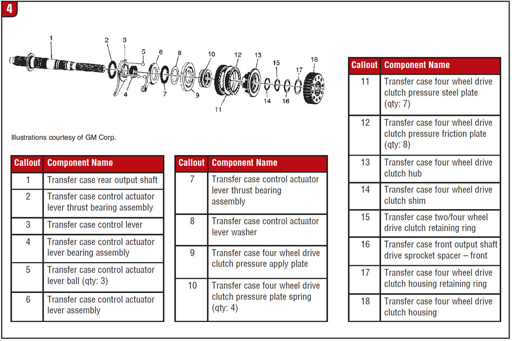
The MP3023 has two variations based on which transmission it is used with, and both are considered light-duty. Version 1 is found behind the M30 (4L60-E) and has a 27-spline input shaft, a 32-spline output shaft and a three-pinion planetary. Version 2 is found behind the M99 (hybrid transmission) and has 32-spline input and output shafts and a three-pinion planetary. The MP3024 is a heavy-duty transfer case found behind the MYD (6L90) transmission and has a 29-spline input shaft, a 31-spline output shaft and a five-pinion planetary. There are other internal differences, which makes parts swapping a tricky proposition (figures 2, 3 and 4). Note: All three variations use a gasket between the transmission and transfer case that must be installed dry with no lube or RTV silicone.
Another design difference from previous models like the NVG246 is the electronic shift motor. Past models used an encoder/shift motor that was one piece to initiate shifts and apply the clutches.
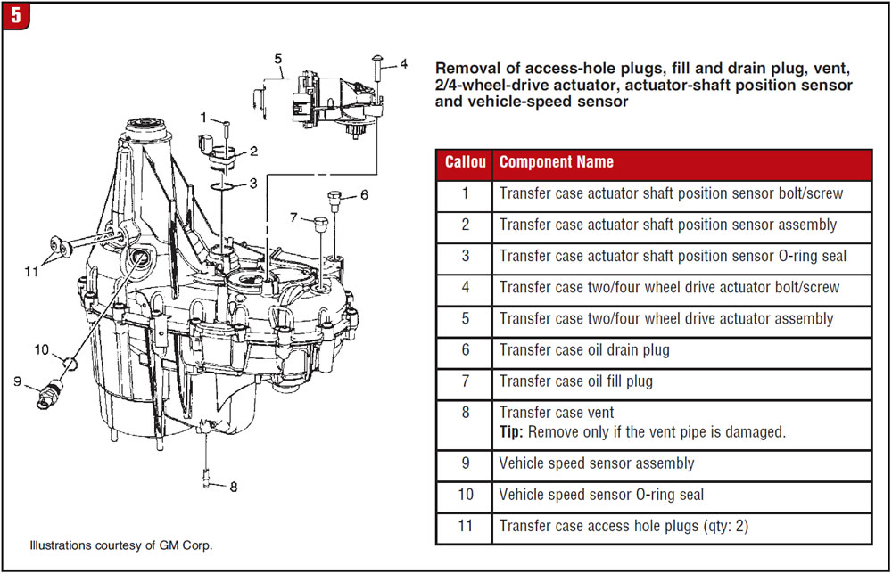
The MP3023/3024 uses an electric shift-actuator motor to shift the unit and apply the clutches but is equipped with a separate actuator-shaft-position sensor assembly (Figure 5) that signals motor position in increments of degrees. The actuator motor is also equipped with a transfer-case motor lock, used to lock the motor in the selected shift position. Energizing the circuit for the lock permits the motor to turn. When the position selected is reached, the circuit turns off and the motor will remain locked in that position. In the A4WD position the motor is locked until a demand for torque application to the front axle is encountered. The motor will then be released to apply the internal clutch pack and send power to the front axle.
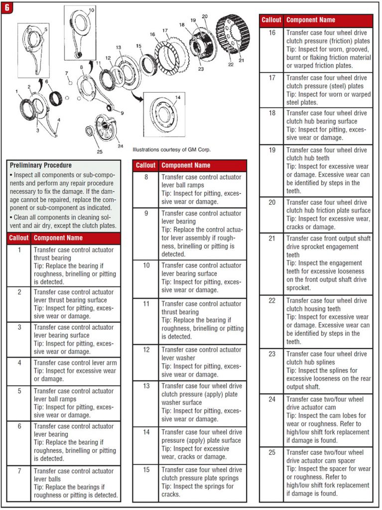
In past models like the NVG246 the encoder/motor applied the clutch pack through a clutch fork internally mounted in the transfer case. In the MP 3023/3024 the clutch application fork is eliminated and replaced by a clutch actuator shaft with a cam that engages an actuator lever, which uses a ball-and-ramp system to apply the clutches (Figure 6), similar to the operation of the BW4405/4411 transfer cases. As the balls travel up the ramp they apply force to the clutch-application pressure plate, locking the clutches.
A series of Belleville springs release the clutch engagement when the duty cycle returns to normal. Note the correct stacking of the Belleville springs in Figure 7.
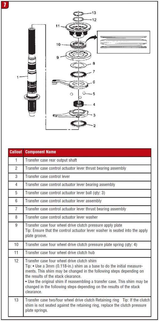
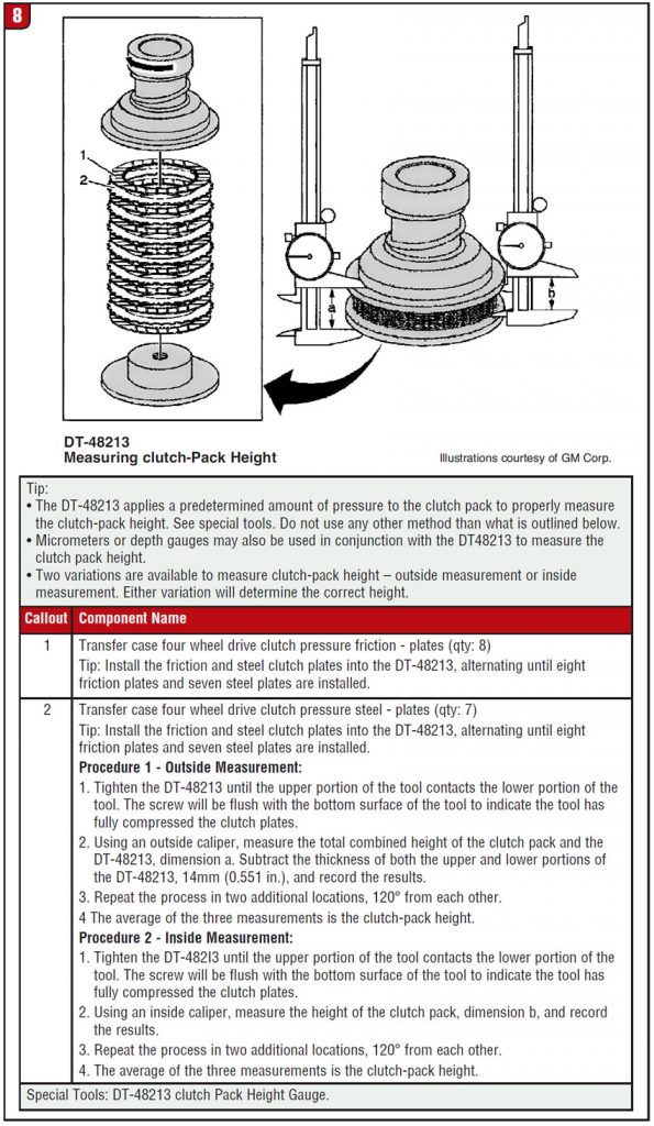
The clutch pack has adjustable shims to adjust the clutch stack height. The shim is under the snap ring that retains the assembly to the output shaft. The repair manual requires a special tool, #DT-48213 (Figure 8), to set the required clutch clearance with a vernier caliper. The clutches are stacked on the bottom plate of the tool and the upper spring-loaded section of the tool is then tightened until it bottoms on the lower part of the tool. Three measurements externally or internally are taken at 120° around the tool, and the average of the three measurements is the stack height of the clutch pack to determine the correct shim to be used. A good rule of thumb is to always start with the original shim size, which usually measures 3mm (0.118 inch).
These units may be a departure from past designs, but they still operate in the same fashion. Understanding the theory of operations will make repairs easier. Next month we will look at the electronics and figure out the trouble codes and their causes. This is usually the most-labor-intensive part of diagnosing problems with any active transfer case.