
Technically Speaking
- Author: Wayne Colonna, Technical Editor
- Subject Matter: Toyota K313 CVT
- Issue: Disassembly
After disassembly, the unit reveals damage
Third and final installment
Last month we removed the pump from the main case and looked at its unique design. Looking back at the transmission with the pump removed, the forward clutch drum assembly comes into view (Figure 1). The outer lugs on the drum are used to excite the turbine shaft speed sensor. The rpm signal from this sensor can be compared to the engine rpm signal to monitor converter clutch apply. Like a conventional transmission, when the clutch is fully applied, both values should be identical.
When the forward clutch drum assembly is removed, it can be seen that the sun gear is integral to the drum assembly (Figure 2). The forward clutch frictions spline to the pinion carrier which when applied will drive the carrier at turbine (input) speed. With the sun gear also spinning at input speed, the entire planetary gear set locks and will rotate at turbine (input) speed. The carrier has a short shaft that splines to the primary pulley. The primary pulley also has a speed sensor. This means the turbine shaft speed and primary pulley speed should have a zero ratio difference if the forward clutches are not slipping.
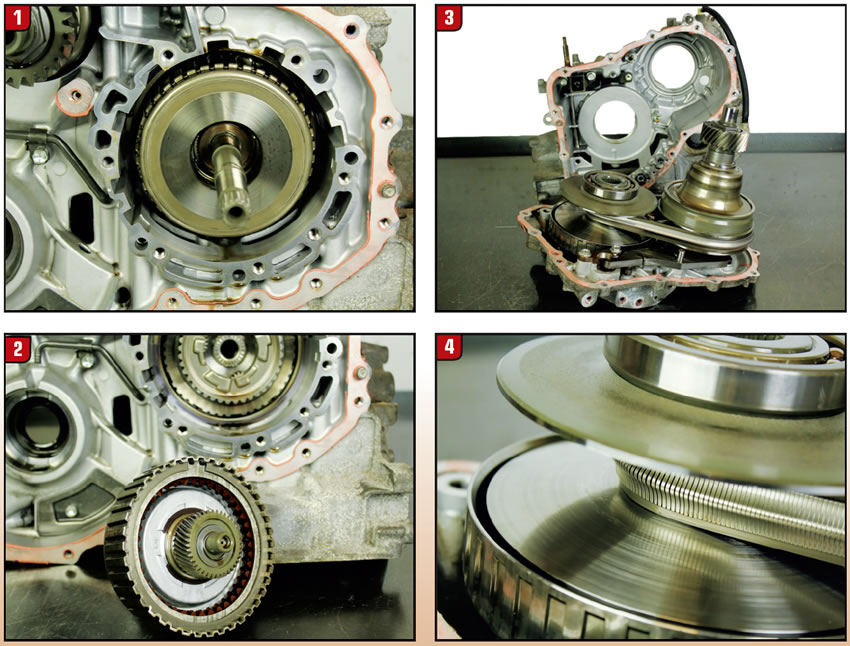
Once the simple planetary set and reverse brake stack-up is removed, the main case can be separated from the variator mounting cover exposing the variator (Figure 3). There is an interesting aspect to the sheave face of these pulleys when you take a close look at them (Figure 4). It has very fine spiral grooves in it like a phonograph record (Figure 5), which is purposely designed. Using a push belt design that has 9 or 12 bands holding all the elements, the fluid used needs to be able to hold torque and lubricate. This is quite a balancing act. The idea behind the spiral grooves is to allow the sheave face and push belt to hold torque transfer while being slippery enough to assist in reducing band to element wear.

As with many other CVTs, the secondary pulley contains the high-tension spring, which needs to be compressed using a special tool like the one seen in figure 5. It is wise to wrap wire ties on the push belt to hold it together so when removing it from the pulleys, the bands and elements do not separate. Two bolts hold the primary pulley assembly to the variator mounting cover while 3 bolts hold the secondary. When the bolts are removed, you’ll notice they use O-rings for sealing (Figure 6). Once these bolts are removed the primary and secondary pulley assembly can be separated from the mounting cover (Figure 7).
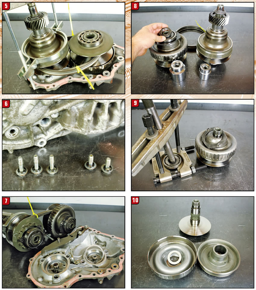
Once the pulleys and belts are separated, the nuts on the pulleys can be removed (Figure 8). Without having a high-tension spring in the primary pulley, a simple bearing puller is all that is needed to disassemble it (figures 9 and 10). A close look at the sheave face of the primary pulley reveals damage (Figure 11). This was due to the owner trying to get out of the snow that ultimately overheated the transmission. You will notice that the damage is isolated to the inside wrap of the pulley. This makes sense as it is the low ratio area of the primary pulley. As the driver was rocking the car between drive and reverse, the belt began to slip in this area to due to the abuse. I’m sure it didn’t help any when line pressure was compromised due to a melting filter.
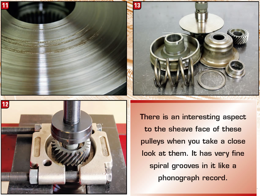
Taking the secondary pulley apart requires a bit more care since it does contain the high-tension spring (figures 12 and 13). This can be safely disassembled using a hydraulic or arbor press, and once apart, just like the primary pulley, there is only one seal on the piston.
It’s a very simple little CVT.


