Technically Speaking
- Author: Wayne Colonna
- Subject Matter: Toyota K313 CVT
- Issue: Fighting snow, overheating
A look at the unit by focusing on one that overheated when fighting snow
First in a series
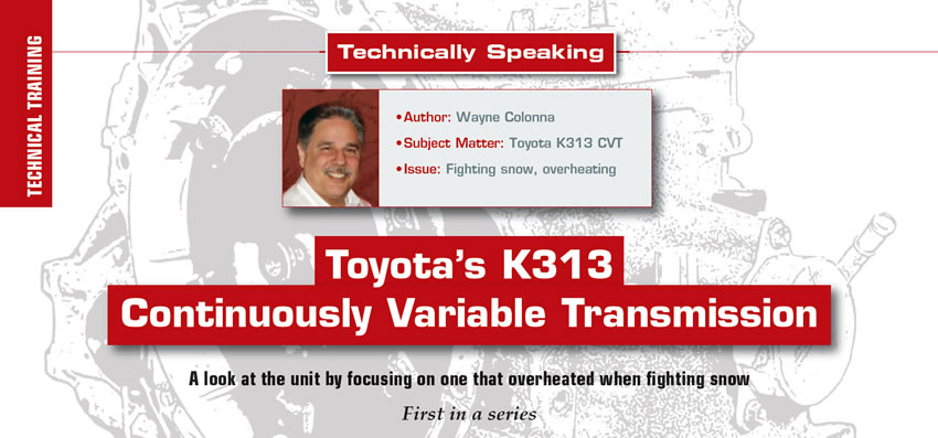
In 2014, Toyota introduced the K313 Continuously Variable Transmission (Figure 1) in their 1.8L Corollas vehicles. It utilizes a torque converter eliminating a forward or reverse clutch-release strategy when in gear at a complete stop.
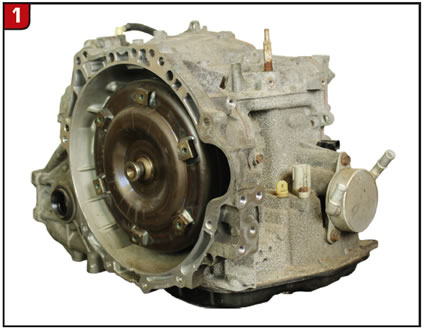
The torque converter neck is a double-ear drive design that indexes into the inner pump gear as seen in Figure 2. As a side note: you may also notice that the converter is overheated with front seal material melted onto the neck. This particular transmission came into a shop in New York leaking out the front. The vehicle had gotten stuck in the snow and the driver tried rocking it out by alternately selecting drive and reverse. This became quite a task, fighting the snow with both traction and vehicle stability control being activated. This aggressive approach to freeing the car caused the transmission to overheat. This overheat was severe enough to melt several items with the front seal being one of them. Jaime Sanzetenea from RJT Motorist in White Plains N.Y. obtained a replacement unit and was able to give this transmission to ATSG. We thank him for his generosity.
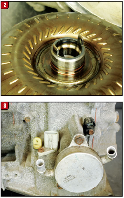
Returning back to getting acquainted with this little CVT box, externally, the primary pulley speed sensor (NIN) is located in the case above the fluid warmer/heat exchanger (Figure 3). This sensor is an AC voltage pulse generator type. The secondary pulley speed sensor (NOT/NOUT) is located on the back cover (Figure 4). This is a two-wire Hall Effect sensor supplied with approximately 5 volts on one circuit and a ground on the other. The secondary pulley pressure sensor can be found on the back cover below the secondary pulley speed sensor as seen in Figure 5. The main fluid fill plug is also located in the rear cover (Figure 6) where nearly 8 quarts (7.5L) of Toyota’s genuine CVT fluid FE can be put into this transmission to fill this box. In Figure 3, an additional fill plug can be seen to the left of the transmission case connector. The main fill plug on the rear cover is a better access point. The pan contains the fluid level check and drain plug as seen in figures 7 and 8.
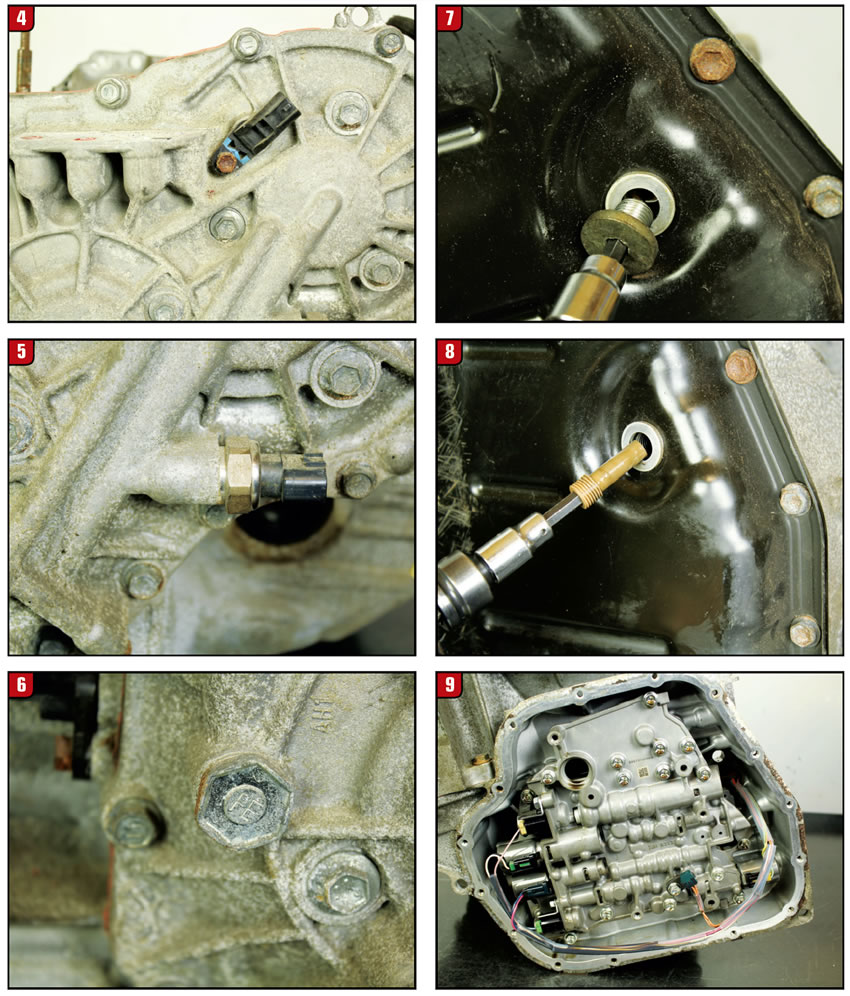
With the pan and filter removed, a fluid-temperature sensor can be seen and a total of 5 solenoids mounted in the valve body are used to operate this transmission (Figure 9).
Due to the overheating condition this transmission experienced, I thought to toss in figures 10 and 11 to show you how badly the filter neck melted down. Figure 12 is a picture of a good filter for comparison. This certainly didn’t help that converter any!
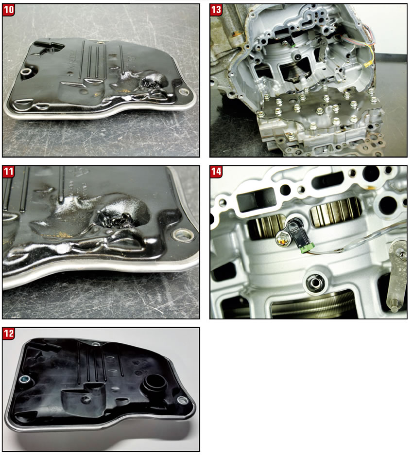
With the valve body removed, the turbine shaft speed sensor (NT) can now be seen (figures 13 and 14). Like the secondary pulley speed sensor, this also is a two-wire Hall Effect sensor supplied with approximately 5 volts on one circuit and a ground on the other.
Next month’s article will get a look at the inside of this box.
DTC list
P0705: Transmission range sensor circuit malfunction (PRNDL input)
P0711: Transmission fluid temperature sensor “A” circuit range/performance
P0712: Transmission fluid temperature sensor “A” circuit low input
P0713: Transmission fluid temperature sensor “A” circuit high input
P0715: Input/turbine speed sensor “A” circuit
P0717: Input/turbine speed sensor “A” circuit no signal
P0720: Output speed sensor circuit
P0722: Output speed sensor circuit no signal
P0741: Torque converter clutch solenoid performance (shift solenoid valve SL)
P075B: Shift solenoid “G” performance or stuck off
P0841: Transmission fluid pressure sensor “A” performance
P0842: Transmission fluid pressure sensor/switch “A” circuit low
P0843: Transmission fluid pressure sensor/switch “A” circuit high
P099B: Shift solenoid “G” control circuit low (shift solenoid valve SC)
P099C: Shift Solenoid “G” control circuit high (shift solenoid valve SC)
P1585: Acceleration sensor circuit
P1586: Acceleration sensor malfunction
P1589: Acceleration sensor learning value
P2757: TCC pressure control solenoid performance (shift solenoid valve SLU)
P2759: TCC pressure control solenoid control circuit electrical (shift solenoid valve SLU)
P2767: Input/turbine speed sensor “B” circuit no signal
P2769: Short in torque converter clutch solenoid circuit (shift solenoid valve SL)
P2770: Open in torque converter clutch solenoid circuit (shift solenoid valve SL)
P2820: Pressure control solenoid “J” performance or stuck off
P2822: Pressure control solenoid “J” electrical (shift solenoid valve SLP)
P2829: Pressure control solenoid “K” performance (shift solenoid valve SLS)
P282B: Pressure control solenoid “K” electrical (shift solenoid valve SLS)
U0124: Lost communication with lateral acceleration sensor module
U0129: Lost communication with brake system control module


