
Issue Summary:
- When a 4L60-E fails from lack of lubrication, the cause may be that the lube-from-cooler passage in the pump stator was not drilled completely.
- We also have information on the bellhousing changes in the 4L60-E units in Camaro and Firebird models, along with the converter applications. None of the parts listed will interchange with previous-design parts.
- In vehicles with the Ford CD4E and Mazda LA4A-EL, high-gear starts in manual low after replace-ment of a valve body or computer could be due to the difference in solenoid firing order between 1994-and-earlier and 1995-and-later vehicles.
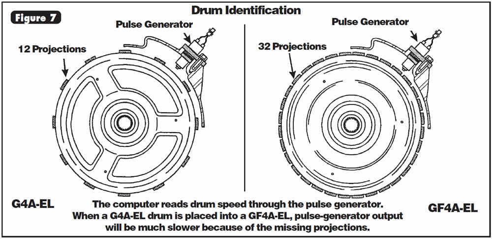
- In a Mazda/Ford GF4A-EL, no 4th gear after rebuild could be caused by installing the forward and coast drum from a G4A-EL. We also have information on harsh upshifts.
- We have identification of lower valve bodies on Mercedes-Benz 722.5 units showing the differences between the models that have rear pumps and those that don’t.
- Also included are information on and functions of the vehicle-speed sensor on the Isuzu NPR/GMC Forward Tiltmaster.


Vehicle is brought to your shop with a transmission that has failed because of lack of lubrication. You check the cooler or possibly replace the cooler as a precaution. After you have replaced the failed parts, the vehicle returns with the same problem.

The cause may be a defective OE pump cover (stator) in which the lube-from-cooler passage was not drilled completely through (See Figure 1). If this passage is not drilled through, there will be no lubrication to the rear of this unit, as all lube must pass through the pump cover. Every one that we have encountered – and we have seen several – had been drilled just deep enough that the cup plug to seal this passage after drilling could be installed in the cover.
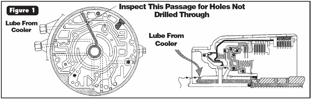

Replace the pump cover as necessary with a new one, and inspect every one that enters your shop to ensure no return failures. All of the defective pump covers we have seen so far were the 13-vane variety.


Beginning in the 1998 model year, General Motors added a new-design bolt-on bellhousing that is about 1⁄2 inch deeper than the previous design. The best identification is the added bolt hole at the top of the bellhousing, as shown in Figure 2.
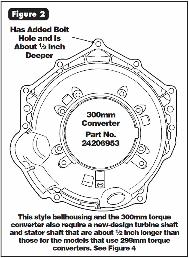
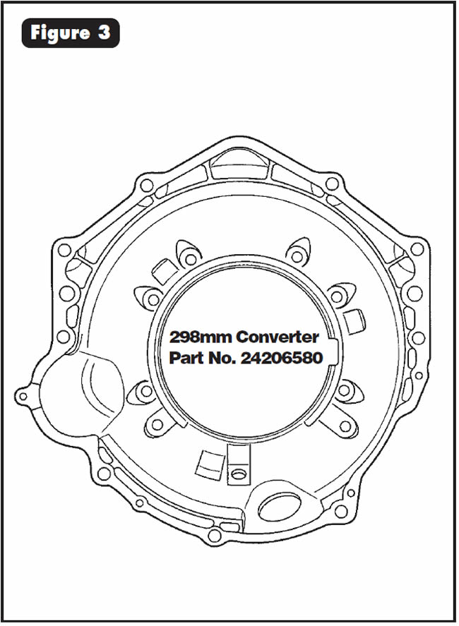
The new-design bellhousing is designed to accommodate a new 300mm torque converter and in the 1998 model year was used in only the Firebird and Camaro. All other models in 1998 used the 298mm converter, which required the bellhousing shown in Figure 3. GM now uses the 300mm converter in many more models.

To accommodate the new 300mm torque converter.

- (1) Bellhousing – Now has an added hole at the top of the bellhousing and is about 1⁄2-in. deeper to accommodate the new 300mm torque converter (See Figure 2).
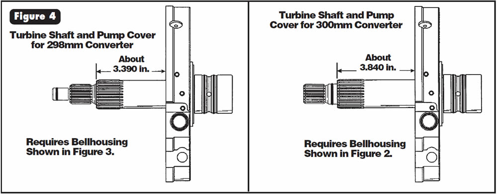
- (2) Pump Cover – Now requires a stator shaft that is about 1⁄2-in. longer to accommodate the new 300mm torque converter (See Figure 4).
- (3) Turbine Shaft – Now is longer and has the O-ring behind the splines, as illustrated in Figure 4, to accommodate the new 300mm torque converter.

None of the parts listed will interchange with previous-design parts. The 300mm torque converter must be used in the models for which it was intended, and the 298mm torque converter must be used in the models for which it was intended.

After replacement of the valve body or computer, pulling the shifter to manual 1 (low) results in a high-gear (fourth) start.
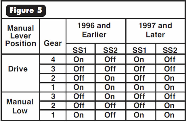
One possible cause is that 1996-and-earlier vehicles use a different solenoid firing order when in manual low because they use a pull-in valve. 1997-and-later vehicles do not have a pull-in valve and use the same solenoid commands in all ranges. Using the wrong valve body or computer will cause this problem.
The recommended solution is to use the correct valve body or computer for the vehicle. If this cannot be accomplished, keeping the accumulator section of the valve body matched with the computer will solve the problem.
To determine which computer the vehicle has, check the actual solenoid commands using a TranX or test lights. Compare your test results with Figure 5 to determine which computer you have.
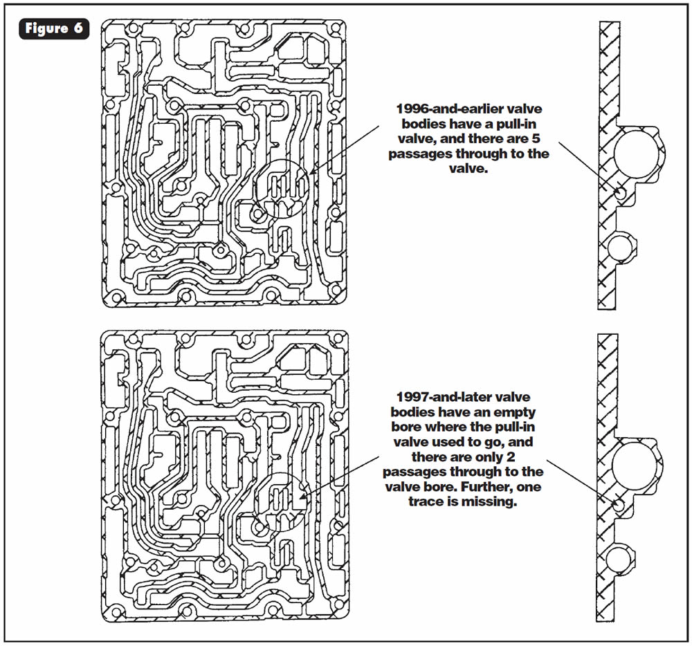
To determine which valve body the unit has, compare your valve body with those shown in Figure 6.


Vehicles equipped with GF4A-EL transaxles may have no 4th gear after overhaul.
The cause may be that a 12-projection G4A-EL reverse, forward and coast drum was installed into a GF4A-EL application that requires a 32-projection drum. When this happens, the computer will not command 4th gear because of the missing projections, which results in a lower drum-speed signal to the computer.
To correct this condition, refer to Figure 7 for drum identification and ensure that the 32-projection drum is installed on all GF4A-EL applications.

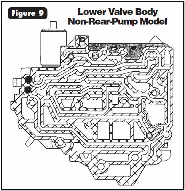
The following information is intended to show the differences between the 722.5 lower valve body for rear-pump models and for models without the rear pump, as well as small-parts locations.
The lower valve body shown in Figure 8 is for a unit with rear pump, and the lower valve body shown in Figure 9 is for a model with no rear pump.
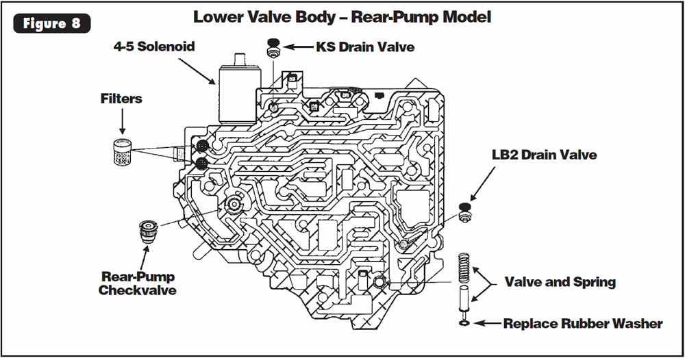
In Figure 8 the rubber washer at the bottom of the valve and spring often gets lost, and the fact that it is missing can go unnoticed.
Thanks to Mario Aristides for his technical assistance in compiling this information.

Vehicles equipped with GF4A-EL transmissions may exhibit harsh shifts, accompanied by trouble code 56 or OBD-II code P0710, transmission-temperature-sensor fault.
Note:
These trouble codes may not flash the MIL (malfunction indicator lamp).
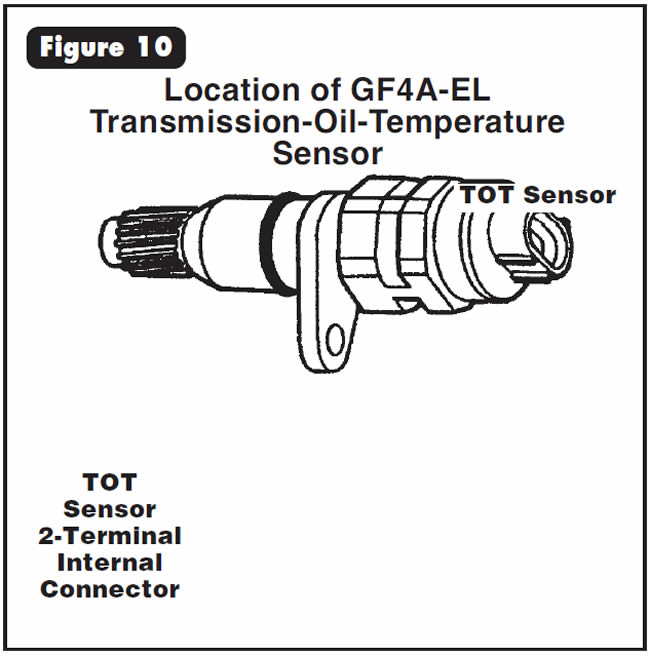
The cause may be a faulty transmission-oil-temperature (TOT) sensor. Vehicles equipped with GF4A-EL transmissions have a computer strategy that commands maximum line pressure when fluid temperature is at or below 10° F. Therefore, if the TOT sensor is faulty, it may indicate that the oil temperature is at or below 10° F at all times.
See Figure 10 for the location of the transmission-oil-temperature sensor.
See Figure 11 for the resistance values and testing procedure to check the sensor.
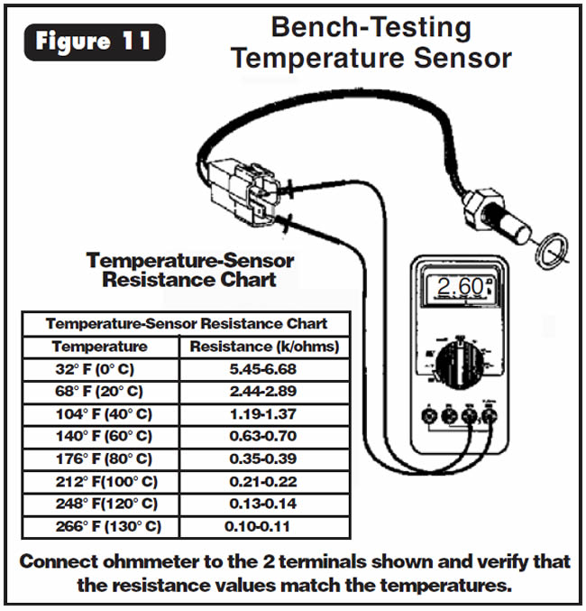
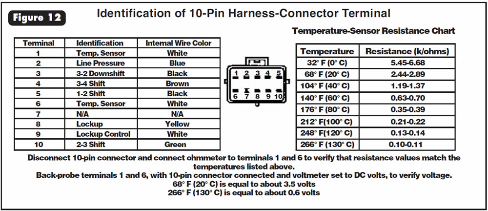
Figure 12 shows the procedure for testing the sensor at the 10-pin connector. Repair or replace the temperature sensor as necessary.

- Transmission-Oil-Temperature Sensor (Mazda) FU2B-19-012B

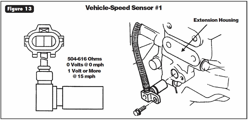
Vehicle-Speed Sensor #1
Vehicle-speed sensor #1 is in the extension housing of the transmission (See Figure 13) and is excited by the parking gear. VSS #1 is an AC-voltage generator and can be checked in AC volts or Hertz (Hz). Usually, you should see more than 1 volt AC at 15 mph. The resistance of the sensor is 504-616 ohms. This sensor is hard-wired to the TCM.
Vehicle-Speed Sensor #2 (1988-94)
Vehicle-speed sensor #2, within these model years, is in the speedometer head and is a reed-switch type that is driven by the speedometer cable (See Figure 14). This sensor is best checked in DC volts at the TCM for a 0- to 5-volt pulse as the rear wheels are rotated slowly.
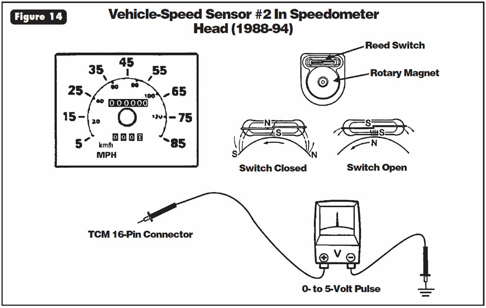
This type of sensor is a three-wire type that has a 5-volt power supply, a ground circuit and a 0- to 5-volt signal return. This sensor has only the signal-return wire going to the TCM.
Note: If VSS #1 fails, VSS #2 will take over control of transmission shift scheduling.
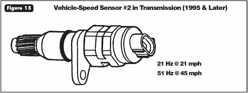
Vehicle-Speed Sensor #2 (1995 & Later)
Beginning with the 1995 model year, VSS #2 was moved to the transmission and became a gear-driven AC-voltage generator (See Figure 15) and can be checked in Hz:
- 21 Hz @ 21 mph
- 51 Hz @ 45 mph
This sensor is hard-wired to the TCM.
Note:
If VSS #1 fails, VSS #2 will take over control of transmission shift scheduling.

June 2001 Issue
Volume 18, No. 6
- THM 4L60-E: Lack Of Lubrication
- THM 4L60-E: Change In Bellhousings for the 1998 Model Year
- Ford CD4E, Mazda LA4A-EL: High-Gear Starts in Manual Low
- Mazda/Ford GF4A-EL: No 4th Gear After Rebuild
- Mercedes Benz 722.5: Lower-Valve-Body Identification
- Mazda/Ford GF4A-EL: Harsh Upshifts (Electrical)
- Isuzu NPR/GMC Forward Tiltmaster: Vehicle-Speed Sensors #1 & #2


