
Issue Summary:
- After overhaul of a 4T65-E, the vehicle does not move after remaining stationary for a prolonged period.
- After transmission exchange or valve-body replacement in a vehicle with a 4T40/45-E, the TCM stores code P1810 for the transmission-fluid pressure-switch assembly immediately after engine start-up.
- Certain Dodge/Jeep trucks with 45RFE/545RFE transmissions may exhibit a complaint of a harsh 2-3 upshift accompanied by a clunk or shudder when accelerating, or a harsh 4-5 upshift or 5-4 downshift.
- Some 1999 Ford F-Series Super Duty vehicles with the 4R100 transmission and 7.3-liter diesel may exhibit what appears to be a flare-up on either the 2-3 or 3-4 upshift.


After overhaul, the vehicle does not move after remaining stationary for a prolonged period. Either the dipstick indicates that the transmission is severely overfilled or there is insufficient transmission cooler flow, neither of which was an original complaint.

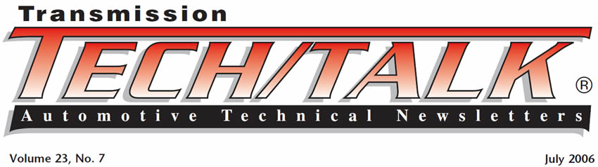
4T65-E transmissions built before Jan. 19, 2004, have the drain-back/cooler blow-off ball and spring in the return-cooler-line case fitting. The channel plate contains only the TCC blow-off ball and spring, as shown in Figure 1.
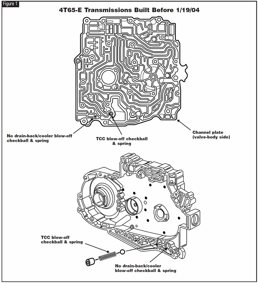
In 4T65-E transmissions built on or after 1/19/04, the drain-back/cooler blow-off ball and spring are in the channel plate next to the torque-converter-clutch blow-off ball and spring, as shown in Figure 2.
These channel plates are not interchangeable but can be switched by mistake. In addition, the cooler-line case fittings were changed at the same time.
Having a drain-back/cooler blow-off ball and spring in both locations could cause too much of a restriction in cooler flow. Having the ball and spring in neither location will cause converter drain-back.

When replacement of the channel plate is required, make certain that the drain-back/cooler blow-off ball and spring are present in their correct location for the build date of the transmission being repaired.
If you install a channel plate without the drain-back/cooler blow-off ball and spring in a transmission with a build date of 1/19/04 or later with the intention of installing the return-cooler-line case fitting that has the ball and spring, this will not work.
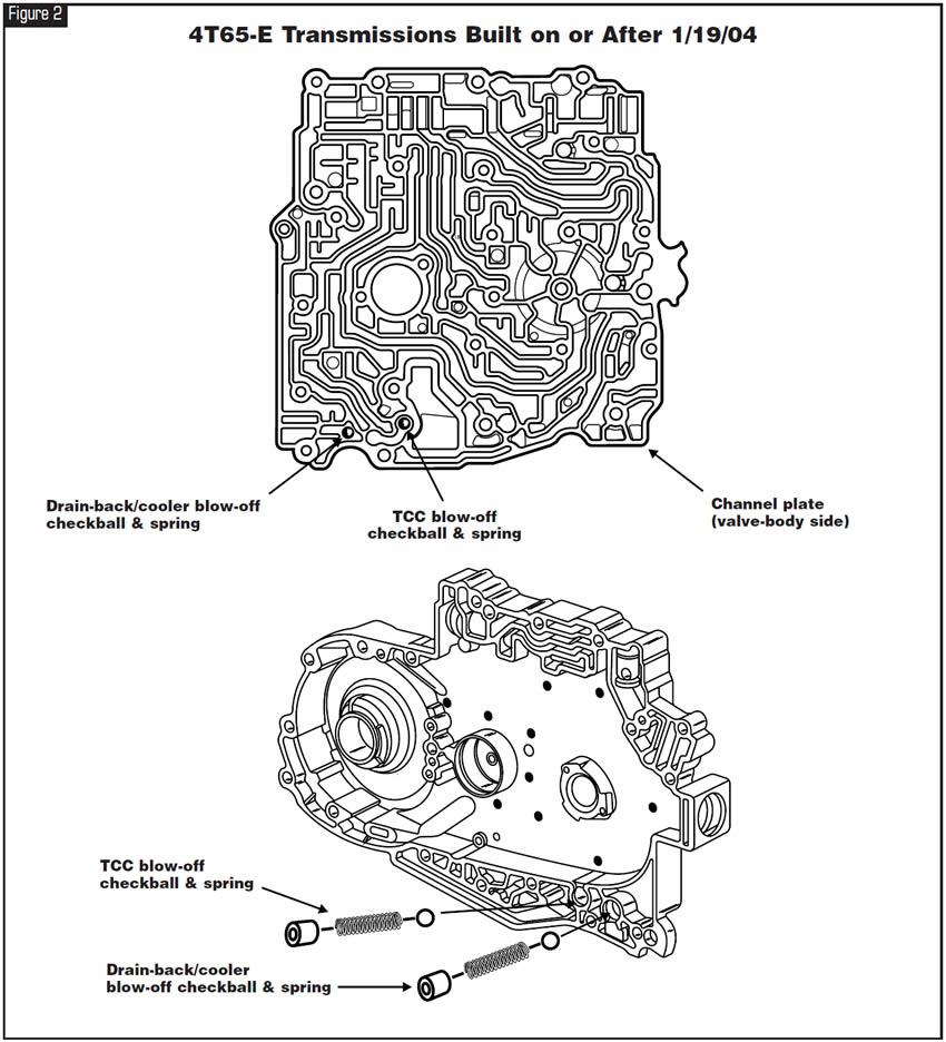
The cooler-line case fittings used before 1/19/04 have different threads. The return-cooler-line case fitting with the ball and spring has a 3⁄8-18 NPSF thread; the supply-cooler-line case fitting has a 1⁄4-18 NPSF thread (refer to Figure 3).
In transmissions built on or after 1/19/04, both cooler-line case fittings are 9⁄16-18 UNF threads, and the return-cooler-line case fitting does not contain a ball and spring (see Figure 3).
Note #1: The function of the drain-back/cooler blow-off ball and spring is to seal the cooler return-oil circuit when the engine is off to prevent converter drain-back, which will cause a delay in forward or reverse movement after the vehicle has remained parked for a long period. It also is meant to unseat and exhaust the cooler circuit should cooler pressure exceed 100 psi.
If the drain-back ball is held off its seat by debris in the system, converter drain-back will occur.
Note #2: The function of the TCC blow-off ball and spring is to unseat and exhaust converter-clutch pressure when it exceeds 100 psi. If the TCC blow-off ball is held off its seat by debris in the system, converter-clutch shudder, slippage or no TCC apply could occur, with trouble code P0741 possibly stored.


After transmission exchange or valve-body replacement, code P1810 for the transmission-fluid pressure-switch assembly (TFPSA) is stored immediately after engine startup.
A 2004 or later transmission or valve body was installed into a 2003 or earlier vehicle.
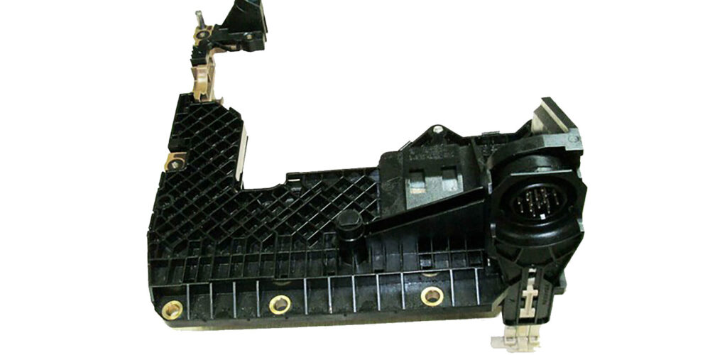
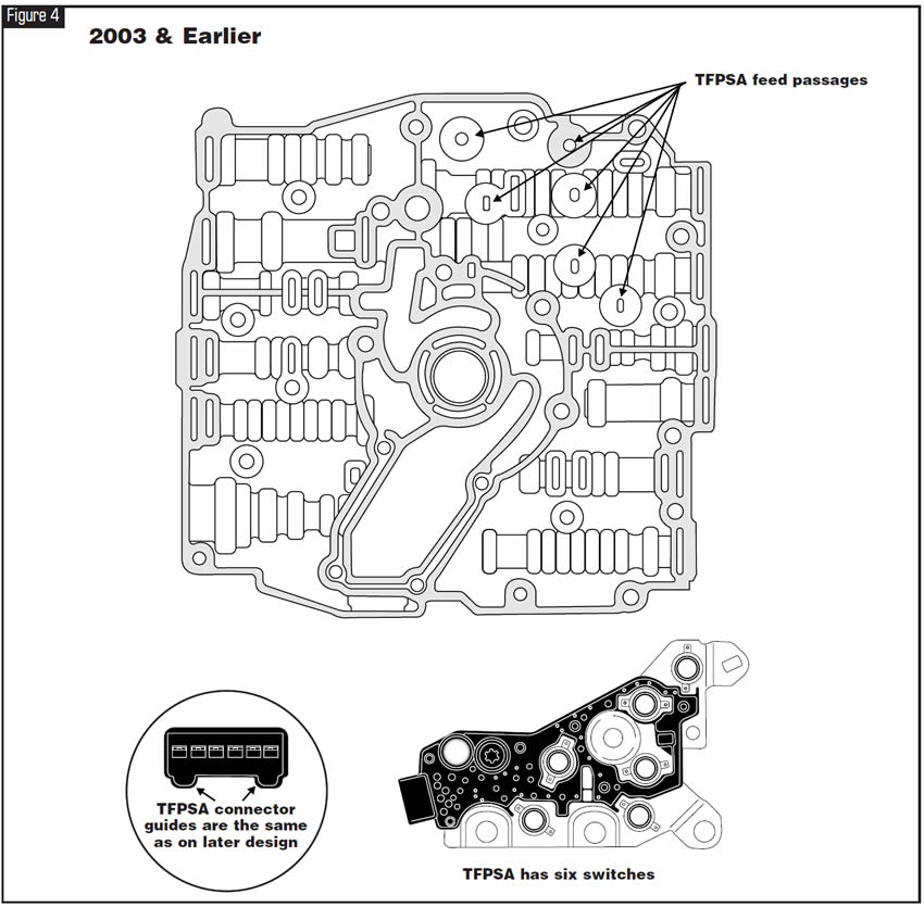
The first-design 4T40-E transmission or valve body uses a six-switch TFPSA (see Figure 4). The valve body has six feed passages, also shown in Figure 4, to activate the various pressure switches in the switch assembly.
At the start of 2004 production a newly designed TFPSA with only three pressure switches (see Figure 5) was used. At the same time, since the pressure-switch feed passages in the valve body no longer were needed, they were cast shut as shown in Figure 5.
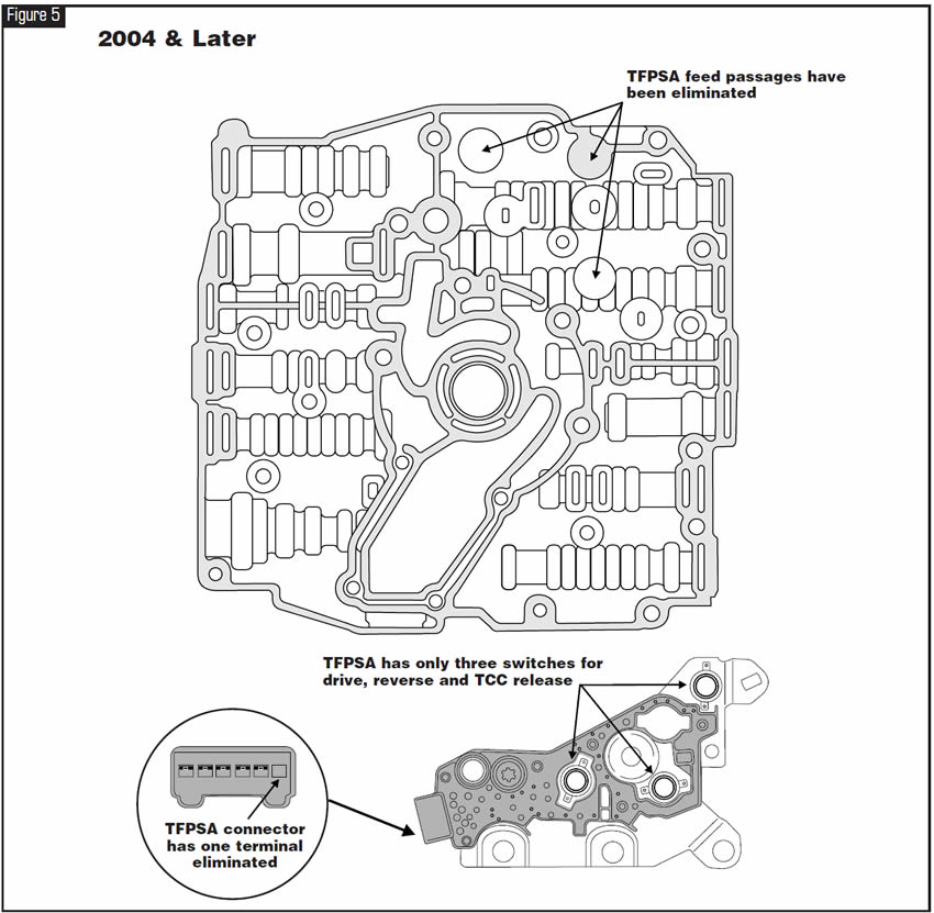
In addition, the pressure-switch-assembly connector cavity is the same for both the early- and late-design units, which you can see in figures 4 and 5. This means the early and late assemblies will connect easily.
When a late transmission is installed into an earlier vehicle, upon ignition cycle the TFPSA has an open circuit because of one less terminal and wire, immediately causing the P1810 code to be stored.

- Transmission-fluid pressure-switch assembly (2003 & earlier) . . . . . . . . . . . . . . . . . . . . .24226580
- Transmission internal wire harness (2003 & earlier) . . . . . . . . . . . . . . . . . . . . .24230346
- Transmission-fluid pressure-switch assembly (2004 & later) . . . . . . . . . . . . . . . . . . . . . . .24217544
- Transmission internal wire harness (2004 & later) . . . . . . . . . . . . . . . . . . . . . . .24229655


2000-01 Dodge Dakotas and Durangos and 1999-2001 Jeep Grand Cherokees equipped with the 45RFE or 545RFE transmission and the 4.7-liter engine may exhibit a complaint of a harsh 2-3 upshift accompanied by a clunk or shudder when accelerating, or a harsh 4-5 upshift or harsh 5-4 downshift (2001 Jeep only).
The TCM or PCM requires a “shift-quality-enhancement” software update.
When all diagnostic procedures have been completed to address these complaints and the complaint is still present, the TCM or PCM will require reprogramming.
This will require a scan tool (DRB III) that is capable of interfacing with the Mopar Diagnostic System 2 (MDS2) to download the necessary revisions.
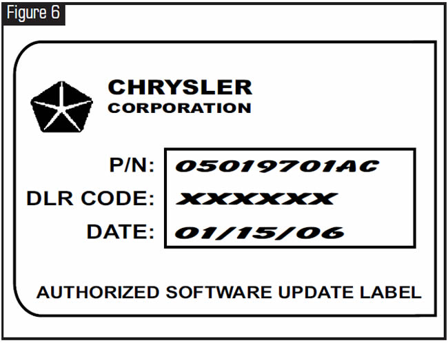
When the reprogramming is complete, an Authorized Software Update Label (see Figure 6) must be placed near the emissions label.
The reprogramming process may cause diagnostic trouble codes to be stored in one or more modules. Be sure to complete the repair by clearing all DTCs.
- 1999-2001 Jeep Grand Cherokee TCM software revision . . . . . . . .PN05019701AC . . . . . . . . . .Version 9.3
- 2000 Dodge Dakota & Durango TCM software revision . . . . . . . . . .PN05018454AB . . . . . . . . . .Version 9.1
- 2001 Dodge Dakota & Durango TCM software revision . . . . . . . . . .PN56028285 . . . . . . . . . . . . .Version 8.4
- 1999 Jeep Grand Cherokee PCM software revision . . . . . . . . . . . .Calibration #99Cal20
- 2000 Jeep Grand Cherokee PCM software revision . . . . . . . . . . . .Calibration #00Cal17

Some 1999 Ford F-Series Super Duty vehicles with the 4R100 transmission and 7.3-liter diesel may exhibit what has been described as a flare-up on either the 2-3 or 3-4 upshift. The rise of engine speed is typically in the range of 200-300 rpm.
The actual problem is not that there is a flare-up during the 2-3 or 3-4 upshift; the complaint results from the PCM strategy that controls the timing of the torque-converter-clutch release during the 2-3 and 3-4 upshifts. This flare feeling is actually the TCC releasing, as commanded by the powertrain control module, during either the 2-3 or 3-4 shift. This has led many technicians to modify and replace accumulator valve bodies, usually with little or no success.
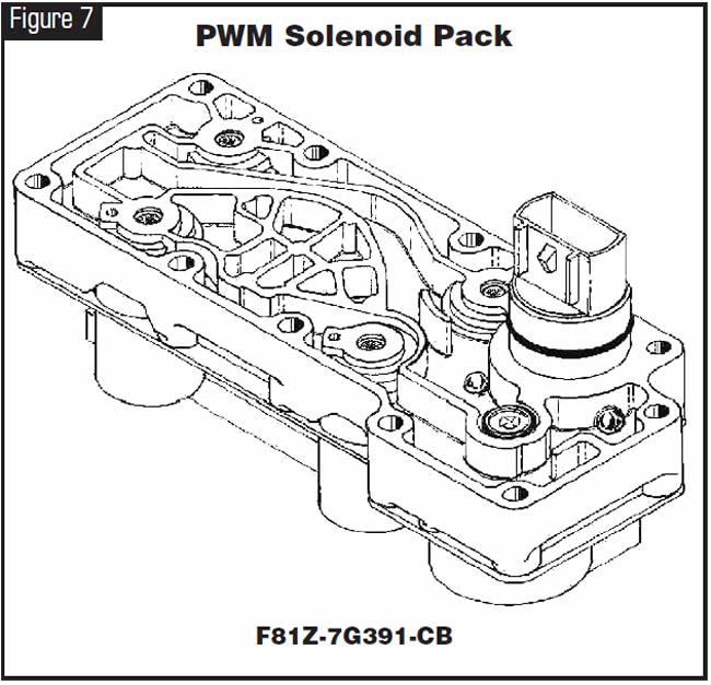
Correcting this condition requires replacement of the solenoid pack (see Figure 7) with the latest revision, Ford part number F81Z-7G391-CB, and reflashing the PCM with the latest calibration per Ford Motor Co. Technical Bulletin 99-8-1.
This correction procedure is for vehicles that are going to retain pulse-width-modulated lockup, not for those that are going to change to an on-off lockup.

July 2006 Issue
Volume 23, No. 7
- 4T65-E: Converter Drain-Back
- GM 4T40/45-E: Code 1810
- Dodge/Jeep Trucks with 45RFE/545RFE Transmissions: Harsh Shifts
- 1999 Ford F-Series Super Duty Diesel: 2-3 and/or 3-4 Shift Flare Before or After Overhaul