
Issue Summary:
- Mismatching wires of the turbine-shaft-speed sensor on Mazda 929 R4A-EL can cause major headaches.
- A timing problem can cause delayed reverse in an E4OD.
- In some two-wheel-drive Ford pickups with the E4OD transmission, stacked upshifts can result from the use of a 4×4 wiring harness.
- We have information on the new A350 unit in the Lexus GS 300.
- Incorrect drive and/or driven sprockets can cause gear-ratio errors in Ford AXODE/AX4S/AX4N units.


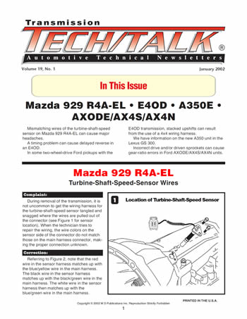
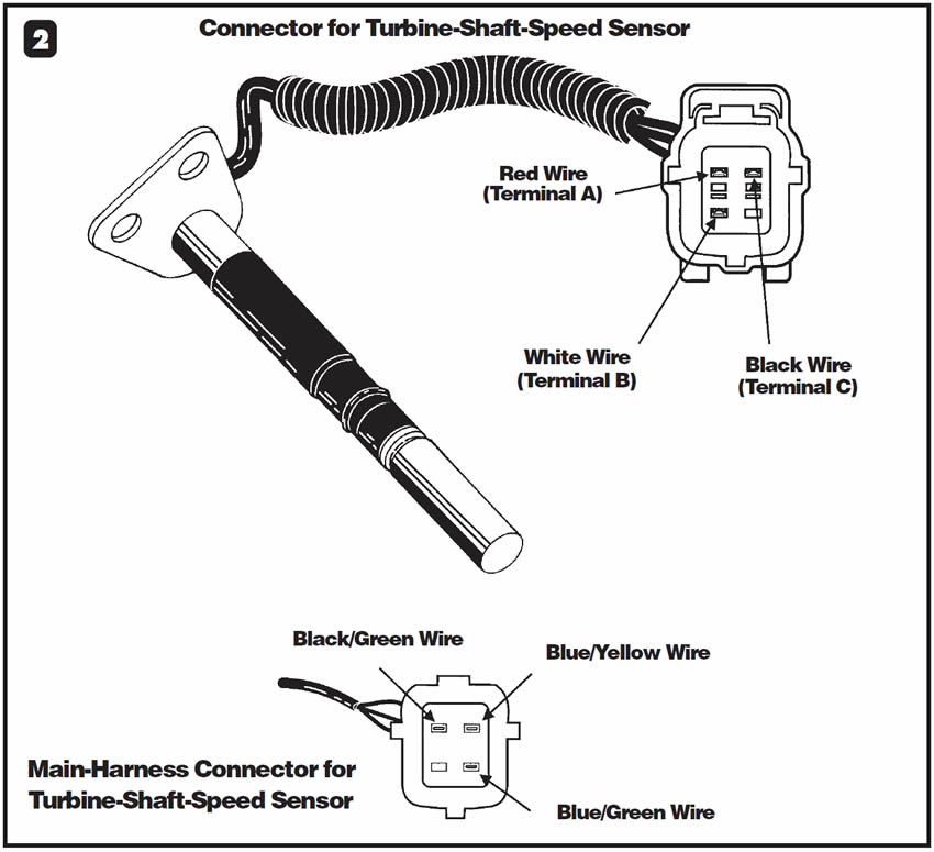
During removal of the transmission, it is not uncommon to get the wiring harness for the turbine-shaft-speed sensor tangled and snagged where the wires are pulled out of the connector (see Figure 1 for sensor location). When the technician tries to repair the wiring, the wire colors on the sensor side of the connector do not match those on the main harness connector, making the proper connection unknown.

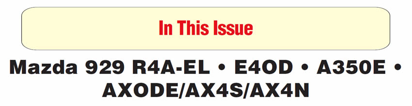
Referring to Figure 2, note that the red wire in the sensor harness matches up with the blue/yellow wire in the main harness. The black wire in the sensor harness matches up with the black/green wire in the main harness. The white wire in the sensor harness then matches up with the blue/green wire in the main harness.


Before or even after overhaul, the transmission experiences a delayed bang shift into reverse.

One reason could be a timing problem that causes the direct clutches to apply before the low/reverse clutch applies. With the direct clutches on first, the geartrain begins to spin, and when the low/reverse clutch finally applies, it stops the geartrain from spinning, resulting in harsh reverse engagement. One possible reason for the late application of the low/reverse clutch is a weak spring on the low/reverse modulator valve, the valve next to the manual valve (see Figure 3).
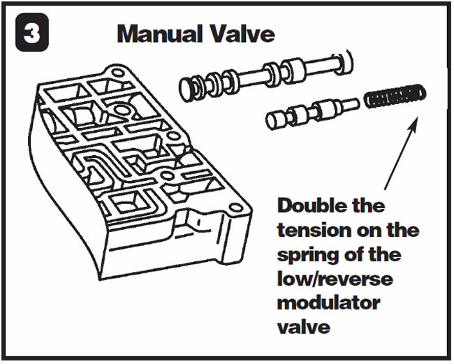
Double the tension on the spring of the low/reverse modulator valve.
Note: A delayed engagement also could occur for the following reasons:
- A loose tension plate on the tail of the spacer plate where the ID notches are.
- A leak in the circuit of the low/reverse, direct or coast clutch.
- Excessive clearance in the low/reverse-, director coast-clutch pack.
- A malfunctioning manual-lever-position sensor
- Low line pressure
- Low fluid level.

Before or after overhaul, the vehicle exhibits rapid upshifts. When the speed sensor is unplugged, the transmission stays in first gear.
Some two-wheel-drive F-Series pickups may have been equipped with 4×4 wiring harnesses. Should the 4×4-low signal wire become grounded in some way, the powertrain control module receives a false signal, causing the rapid upshift. Since the vehicle is two-wheel-drive, the 4×4 parameter may be overlooked.
On 1989 and some 1990 vehicles, using a scan tool will not reveal the cause of the problem, since data stream is not available. On vehicles with data-stream capabilities, you can observe the ON/OFF status of the 4×4 switch through the scan tool. With two-wheel-drive vehicles the status of the switch should be OFF at all times. If you observe an ON status, the wire has been grounded in some way or the PCM is malfunctioning.
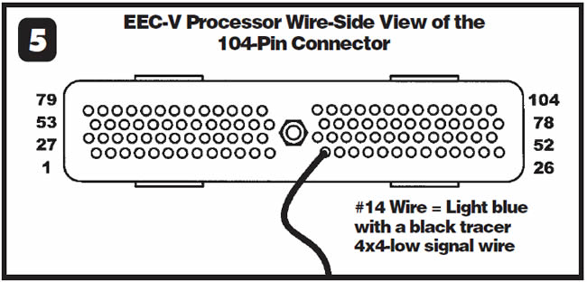
A quick method for deciphering a wire or PCM concern is to locate the No. 12 wire in the 60-pin PCM connector (see Figure 4) or the No. 14 wire in the 104-pin PCM connector (see Figure 5). This is the 4×4 signal wire, and since it is not used on two-wheel-drive vehicles, cut it. The ON/OFF parameter should change to OFF if this wire was shorted to ground, and the vehicle should operate correctly. If the parameter remains ON, the PCM is faulty.
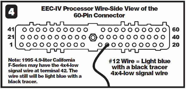
For the early 1989 and 1990 vehicles that do not provide data stream, cut the No. 12 wire (see Figure 4) and take the vehicle for a road test. If the problem remains, you will need to check parameters for engine load, throttle-position sensor and vehicle-speed sensor with a multimeter and verify proper operation before condemning the PCM.


1993-95 Lexus GS 300 vehicles are equipped with the all-too-familiar Toyota A340E transmission. But Toyota decided to do a face lift on this transmission. Why not keep up with the rest of today’s technology? With the redesign for model years 1996 to the present, the transmission comes with a different name –A350E.
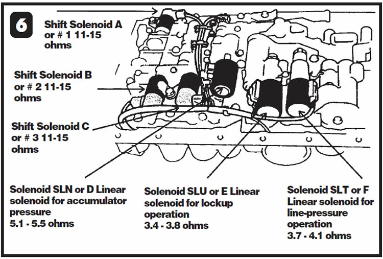
The valve body now sports a gang of six solenoids (see Figure 6). ON/OFF commands to three shift solenoids accomplish shifts from first gear through overdrive. The line-pressure solenoid, lockup solenoid and accumulator-pressure-control solenoid complete the gang.
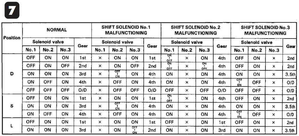
What also is unique to this transmission is the shift strategy. Should one of the solenoids become shorted or open, producing a code, the computer will cancel lockup but continue to shift with the remaining two operable shift solenoids. Depending on which solenoid has failed, this type of shift strategy makes available up to three different shift sequences. The chart in Figure 7 shows the normal shift pattern of the solenoids and the three shift strategies available, depending on which solenoid has failed electrically. If two or more solenoid codes are stored, a limp to overdrive will take place, with second gear available in the manual-low range.
When troubleshooting this vehicle, you need a scan tool to obtain diagnostic trouble codes through the OBD-II connector, which is under the dash by the driver-side kick panel. If a code is stored, the check-engine light in the dash under the temperature gauge should remain on after the engine is started.
Two tips are in order here. One, if this light does not illuminate when the ignition is turned on, check the gauge fuse. This light must come on when the ignition is turned on. If no codes are stored, the light will go out in just a few seconds, indicating that the system is operable. Two, if the light stays on, indicating a code is set, perform three drive cycles. If the problem does not recur after three trips, this light will go out on its own. In other words, if the light is on, stop the vehicle and drive it through all the available gears. Do this three times. If the light goes out, keep your fingers crossed and maybe you’ll have a great weekend. If the light stays on, get the scan tool. The OBD-II codes for the solenoids are:
- P0753 – Shift solenoid 1 (A)
- P0758 – Shift solenoid 2 (B)
- P0763 – Shift solenoid 3 (C)
- P0773 – Linear solenoid SLU
- P1760 – Linear solenoid SLT
- P1765 – Linear solenoid SLN
The computer generates these codes when it observes electrical failure of the circuit, meaning either excessive or insufficient current draw. The ECM also can detect mechanical failures for four of the solenoids. It then will produce specific codes indicating this failure. Keep in mind that these codes indicate either stuck-open or stuck-closed solenoids, but it also may be sticking shift valves as well. These codes are:
- P0750 – Shift Solenoid 1 (A)
- P0755 – Shift Solenoid 2 (B)
- P0760 – Shift Solenoid 3 (C)
- P0770 – Linear Solenoid SLU
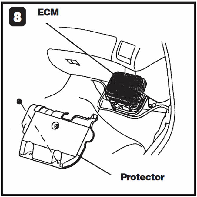
If electrical failure codes exist, resistance checks can be performed at the ECM, which is under the carpet on the passenger side. You have to remove a protective cover to gain access to the ECM (see Figure 8).
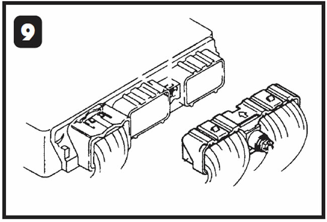
Once you have removed the cover, unplug the larger connector (see Figure 9).
Using a DVOM set to ohms, place the negative meter lead to the No. 69 cavity for ground. Using the chart in Figure 10 as an aid, with the positive lead carefully probe cavity 10 for shift solenoid 1, cavity 9 for shift solenoid 2, cavity 8 for shift solenoid 3, cavity 14 for solenoid SLU and cavity 13 for solenoid SLN. For solenoid SLT, move the negative lead to cavity 12 and the positive lead to cavity 31. The chart in Figure 10 also provides the solenoid resistance values. One other note – the transmission has two separate solenoid harnesses, one with an eight-pin connector and one with a three-pin connector.
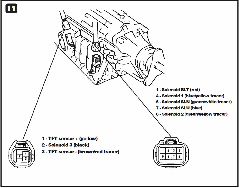
Refer to Figure 11 for views of both vehicle harnesses should you need to make continuity checks from the ECM connector to the transmission connectors.

During the road test after overhaul, the malfunction indicator lamp (MIL) begins to flash and the system defaults to failure-mode-effects management (FMEM). When code retrieval is completed, code 628 for TCC slippage, code P0741 for TCC stuck off or code P1744 for a TCC performance fault may be stored. Diagnosis of the TCC system detects no problems. When these codes are cleared, they return on the next road test.
These complaints can be caused by installing an incorrect drive and/or driven sprocket (see Figure 12) or by installing an exchange unit that does not have the correct number of sprocket teeth. Sprocket-tooth count is what determines the target gear ratio that the PCM should see. Because the PCM is comparing the signals from the engine-speed and turbine-speed sensors, the PCM assumes that the converter clutch is slipping and stores the preceding codes because the incorrect sprocket-tooth count resulted in an incorrect gear ratio.
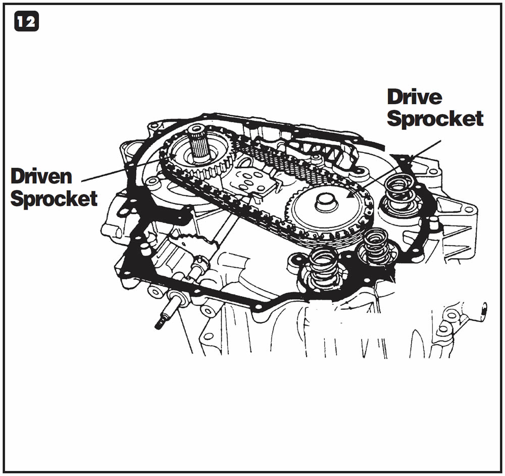
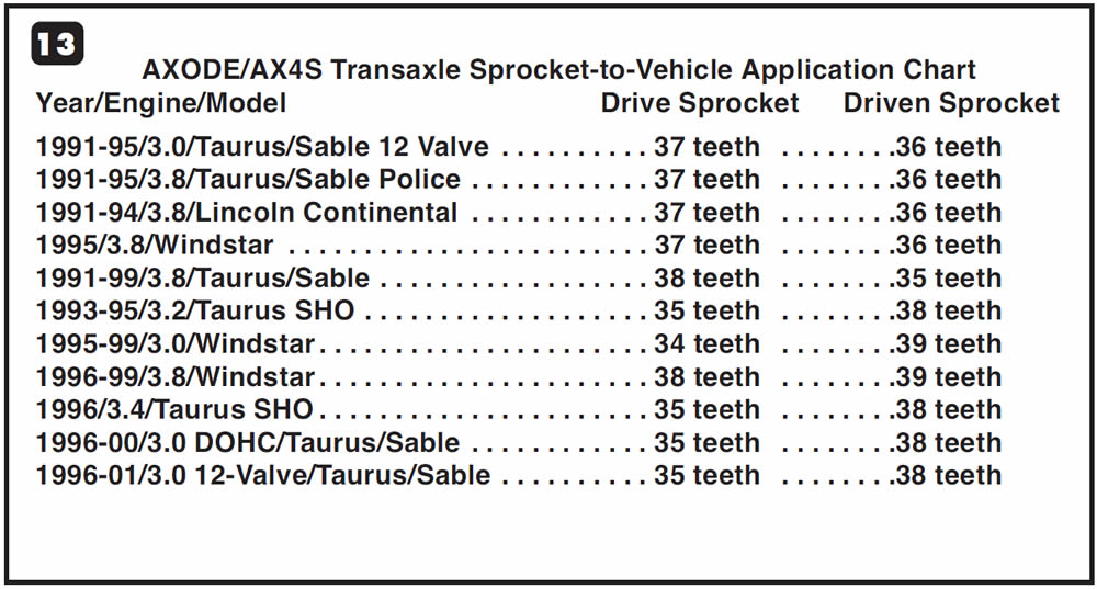
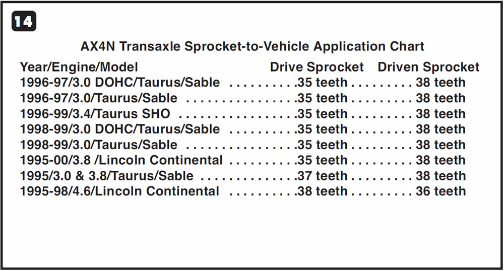
Use the charts in Figures 13 and 14 to ensure that the sprocket-tooth count matches the vehicle application. You also should tag exchange units with their sprocket-tooth counts to ensure installation of the correct transmission in each vehicle.
Special Note:
The AXODE/AX4S chart in Figure 13 is a corrected version indicating the difference in tooth counts between the 1991-95 and 1996-2001 Taurus/Sable with the 12-valve 3.0-liter V-6.
This information was incorrect in the ATSG 2001 RED Seminar Manual.
- Note: To help diagnose this problem, raise the front wheels off the floor and see whether these codes reset with no load on the vehicle. If they do, chances are that the problem is a gear-ratio error and not converter-clutch slip.

January 2002 Issue
Volume 19, No. 1
- Mazda 929 R4A-EL: Turbine-Shaft-Speed-Sensor Wires
- E4OD: Delayed Reverse
- Two-Wheel-Drive Ford Pickups With E4OD: Stacked Upshifts
- Lexus GS 300: A350E Transmission
- Ford AXODE/AX4S/AX4N: Gear-Ratio Errors


