


1992 and later Ford trucks that have LCD odometers and are equipped with either an E4OD, AODE or 4R70W transmission may suddenly go to a neutral condition while being driven, or, after the vehicle comes to a stop, the transmission may be stuck in first gear. The TCIL (transmission-control indicator lamp) flashes as a result, and a scan tool reveals that a code 29, 452, PO500 or PO503 has been stored. These symptoms and erratic speedometer operation may occur intermittently. The codes also may be stored in memory from past intermittent failures or glitches.

These symptoms may be caused by one or more of the following:
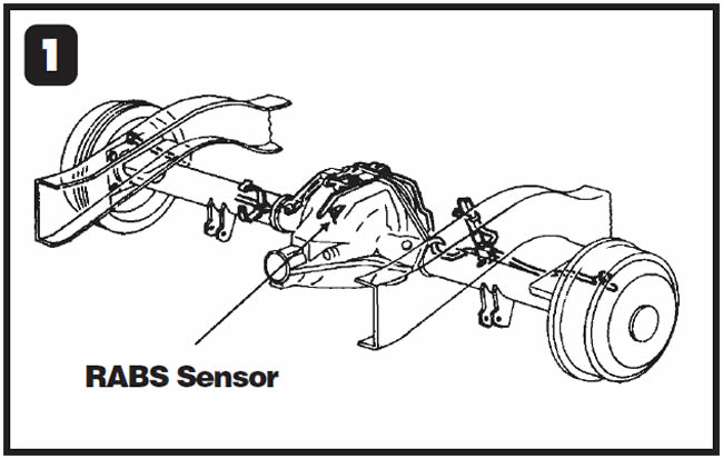
- A faulty vehicle-speed sensor (VSS), known as the rear anti-lock brake-system (RABS) sensor, now in the rear differential (see Figure 1)
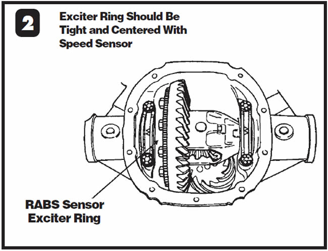
- A loose speed-sensor exciter ring on the differential ring-gear carrier (see Figure 2)
- Excessive use of silicone on the sensor, altering the air gap between the sensor and the exciter ring
- A deteriorated RABS sensor connector or wiring
- A malfunction of the PSOM (programmable speedometer/odometer module)
- A loss of power or ground to the PSOM
- A faulty PCM/TCM (powertrain control module/transmission control module).
The PSOM
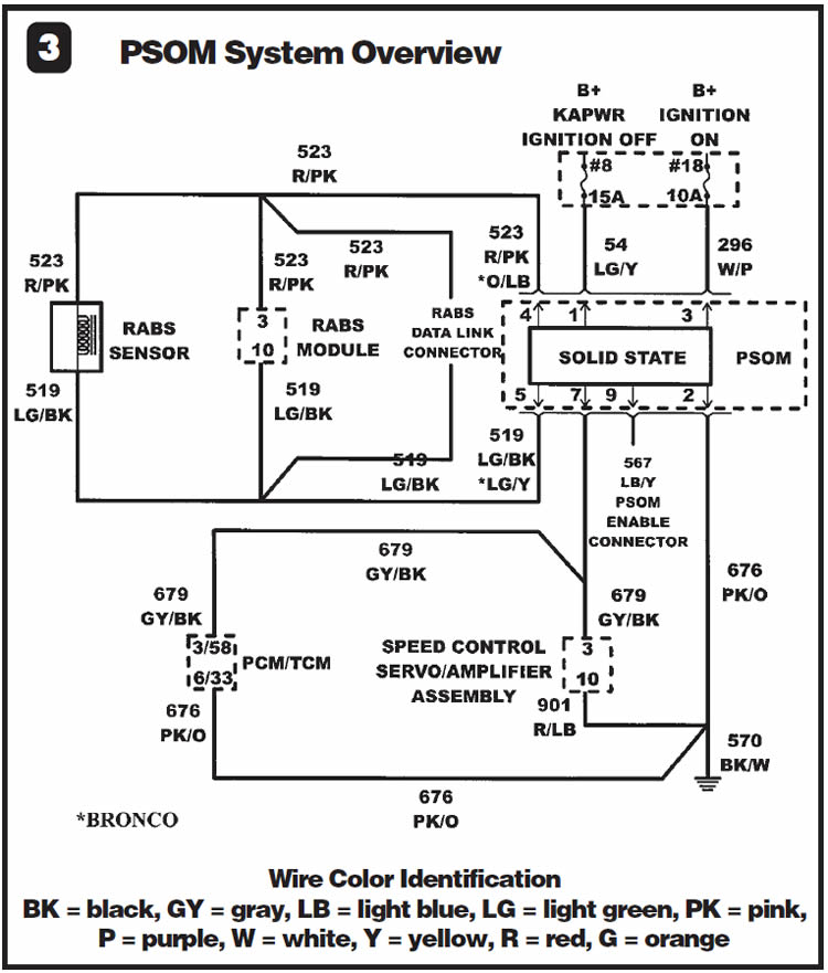
The PSOM’s operation directly affects all shift scheduling! 1992 and later Ford trucks with the VSS, or RABS sensor, in the differential are equipped with an internal microprocessor known as the PSOM within the speedometer cluster that uses a liquid-crystal-display odometer. The PSOM receives an analog signal from the VSS in the form of AC voltage. The signal’s frequency is proportionate to road speed, and the PSOM converts it to an 8,000-pulse-per-mile signal that the PCM/TCM can decipher. The PSOM is calibrated for each vehicle’s tire size and differential gear ratio. A technician can recalibrate the PSOM to accommodate a change in tire size and/or differential gear ratio. Figure 3 shows an electrical overview of the PSOM system. Using the following diagnostic procedures, replace or repair the faulty component.

Step 1: The first step is to question the customer to see whether the problems began after tires and/or the differential was changed. The problem may be as simple as oversized or undersized tires or a changed gear ratio in the differential. If this has occurred, you may need to re-evaluate the situation as to whether it would be best to go back to OE or remedy the change by reprogramming the PSOM to accommodate the modified tire size or differential ratio.
If the problem did not follow a change in tire size or differential gear ratio, road-test the vehicle, taking note of the speedometer and odometer operation for function and accuracy. If DATA is available from a scan tool, compare the speedometer’s speed reading with that of the scan tool. If the scan tool’s reading is correct but the speedometer is erratic and bouncy, the speedometer head is faulty. If readings from both the scan tool and speedometer are bouncy or if DATA is not available for comparison, perform the following checks with the rear wheels off the ground:
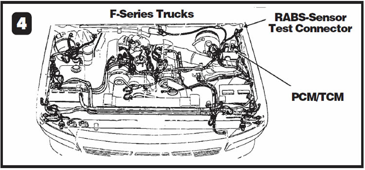
- Locate the two-wire RABS-sensor test connector (red with a pink tracer and light green with a black tracer). On F-series trucks the connector is in the left-rear corner of the engine compartment (see Figure 4).
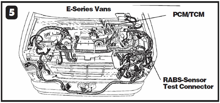
- On E-series vans look behind the driver-side head-lamp assembly (see Figure 5).
- Set your multimeter to hertz, probe the RABS-sensor test connector and increase vehicle speed to 30 mph (48 km/h). The multimeter should indicate about 667 hertz. If the frequency reading is correct, go to step 2. If the frequency reading is erratic, unplug the sensor in the differential and repeat the test at the sensor. If the frequency reading continues to be erratic, the exciter ring in the differential may be loose or the speed sensor may be faulty. If you see a steady 667 hertz directly from the sensor at 30 mph, the sensor’s connector or its wiring to the PSOM is faulty and will need to be repaired or replaced.
Step 2: For F-Series trucks, use Figure 4 to locate the vehicle’s computer, which is to the left of the brake booster. For E-Series vans, use Figure 5, which shows the computer’s location to the right of the brake booster. With the multimeter still set to hertz, back-probe the following wires:
- EEC-IV processors have a 60-pin connector. Back-probe wires 3 and 6. Wire 3 is gray with a black tracer and is known as circuit 679. Wire 6 is pink with an orange tracer and is known as circuit 676.
- EEC-V processors (1994-95 F-Series turbo diesels and 1996 and later vehicles) have a 104-pin connector. Back-probe wires 33 and 58. Wire 33 is gray with a black tracer and is known as circuit 679. Wire 58 is pink with an orange tracer and is known as circuit 676.
Increase vehicle speed to 30 mph (48 km/h); the meter should indicate about 67 hertz. If the reading is correct, the PCM is faulty. If there is no reading or it is erratic or incorrect, the problem could be faulty wiring between the PSOM and the PCM, a faulty PSOM and/or a blown No. 8 or 18 fuse. To locate the problem, you must perform a step-by-step pin check of the PSOM circuits, beginning with step 3.
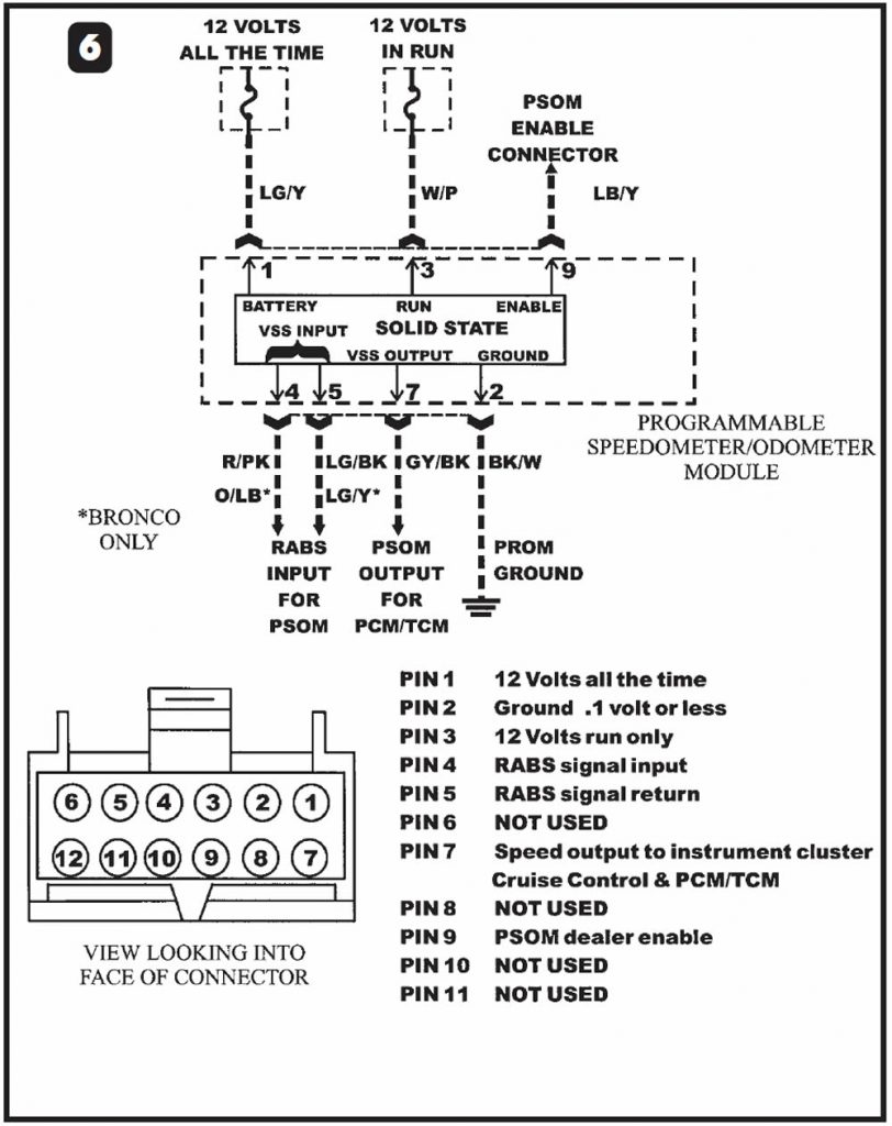
Step 3: Remove the instrument cluster from the dash to gain access to the 12-pin PSOM connector, a diagram of which is at the bottom of Figure 6. See the schematic in Figure 6 for the following pin checks at the PSOM connector.
- Note: If the dash panel has a dual-tank fuel switch, you need to remove the switch from the dash, allowing it to remain plugged into the harness. If this switch is unplugged, the vehicle will not start.
Step 4: With the PSOM connector plugged into the cluster, set a multimeter to DC volts and place the negative lead to a known good ground. With the positive lead, locate and probe the light-green wire with a yellow tracer (circuit 54) at terminal 1 in the PSOM connector. This is keep-alive power and must have full battery voltage even with the ignition off.
If it does, move to step 5. If it does not, inspect the No. 8 15-amp fuse in the fuse box under the dash for power. Figure 7 shows the fuse location.
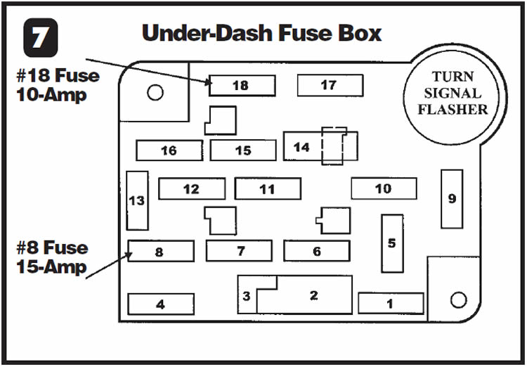
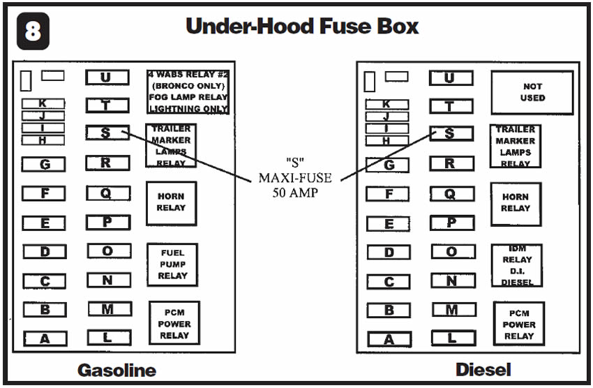
If the fuse is blown, replace it. If it blows again, there is a short to ground in the light-green wire with yellow tracer from the fuse to the PSOM connector, and you will need to replace the wire. If there is power and the fuse is not blown, the light-green wire with yellow tracer from the fuse to the PSOM connector is severed and will need to be replaced. If the No. 8 fuse was not blown and did not have power either, the 5-amp “S” maxi-fuse in the underhood fuse box should be checked and replaced if necessary (see Figure 8 for location). If the maxi-fuse is not blown, either the black wire with an orange tracer between the maxi-fuse and the fuse box under the hood may have been severed or there is an internal problem within the fuse box.
Step 5: Keeping the multimeter set to DC volts and the negative lead to a known good ground, locate and probe the white wire with a purple tracer (circuit 269) at terminal 3 in the PSOM connector. You should see system voltage when the ignition is on. If so, continue to step 6. If not, inspect the No. 18 10-amp fuse for power (see Figure 7). If there is power and the fuse is not blown, the white wire with a purple tracer is severed and will need to be replaced. If the No. 18 fuse was not blown and did not have power either, the ignition switch or the gray wire with a yellow tracer (circuit 687) from the switch to the fuse is faulty and will need to be replaced.
Step 6: With the PSOM connector still plugged in and the multimeter set to DC volts with the negative lead fixed to a known good ground, locate and probe the pink wire with an orange tracer (circuit 676) at terminal 2. This is the PSOM’s ground circuit. With the vehicle running, you should observe no more than 0.3 volt during this voltage-drop test. 0.1 volt or less is best. If this reading is acceptable, move on to step 7. If this reading is higher than 0.3 volt, you must repair or replace this ground wire so that you observe 0.1 volt or less.
- Note: This wire changes to a black wire with a white tracer (circuit 570) after the factory splice.
Step 7: This step verifies the input of the RABS sensor to the PSOM. Step 1 verified that the wiring from the RABS sensor to its test connector was good. This step verifies that the wiring from the test connector to the PSOM is good. To do this, unplug the PSOM connector and set a multi-meter to hertz. With the positive lead, back-probe terminal 4, a red wire with a pink tracer (on Broncos, an orange wire with a light-blue tracer), circuit 523, and the negative lead to terminal 5, a light-green wire with a black tracer (on Broncos, a light-green wire with a yellow tracer), circuit 519. The frequency reading should be about 667 hertz at 30 mph (48 km/h). If so, proceed to step 8. If the frequency reading is unacceptable, you can perform an additional check of the circuit by turning the ignition off and switching the multimeter setting to ohms. This checks the sensor circuit for proper resistance, which is 900 to 2,500 ohms. If frequency or resistance readings are erratic or incorrect or you don’t get readings, use the wire diagram in Figure 3 to isolate and check each wire from the PSOM connector to the RABS-sensor test connector. Repair or replace one or both wires as necessary.
Step 8: This step checks the conditioned signal that the PSOM sends to the PCM/TCM. This requires the PSOM connector to be plugged into the instrument cluster. Place the multimeter to the hertz selection and fix the negative meter lead to a known good ground. Locate the gray wire with a black tracer, circuit 679, at terminal 7 in the PSOM connector and probe it with the positive meter lead. The frequency reading should be about 67 hertz at 30 mph (48 km/h).
If this reading is erratic or severely off, either the PSOM is defective and will need to be changed or the differential gear ratio has changed. If the problem is a change in gear ratio, the correction is recalibration of the PSOM. If this reading is correct and DATA to the scanner reads differently, the PCM/TCM is defective. If DATA is not available but shift scheduling is erratic, chances are the PCM/TCM is defective. If all readings are correct, repeat this test on the road. If readings become altered, a change in tire size may have occurred; you also can recalibrate the PSOM to correct this situation. Refer to the following calibration procedures.


Recalibrating the PSOM
The PSOM requires recalibration when a change in tire size or differential gear ratio has occurred, the speedometer has been serviced, or when a prolonged loss of power to the PSOM has occurred. To recalibrate the PSOM, you will need the following information to calculate the “conversion constant”:
- A) Differential gear ratio
- B) Tooth count of the speed sensor’s exciter ring on the differential
- C) Tire size
Step 1 – Differential Ratio
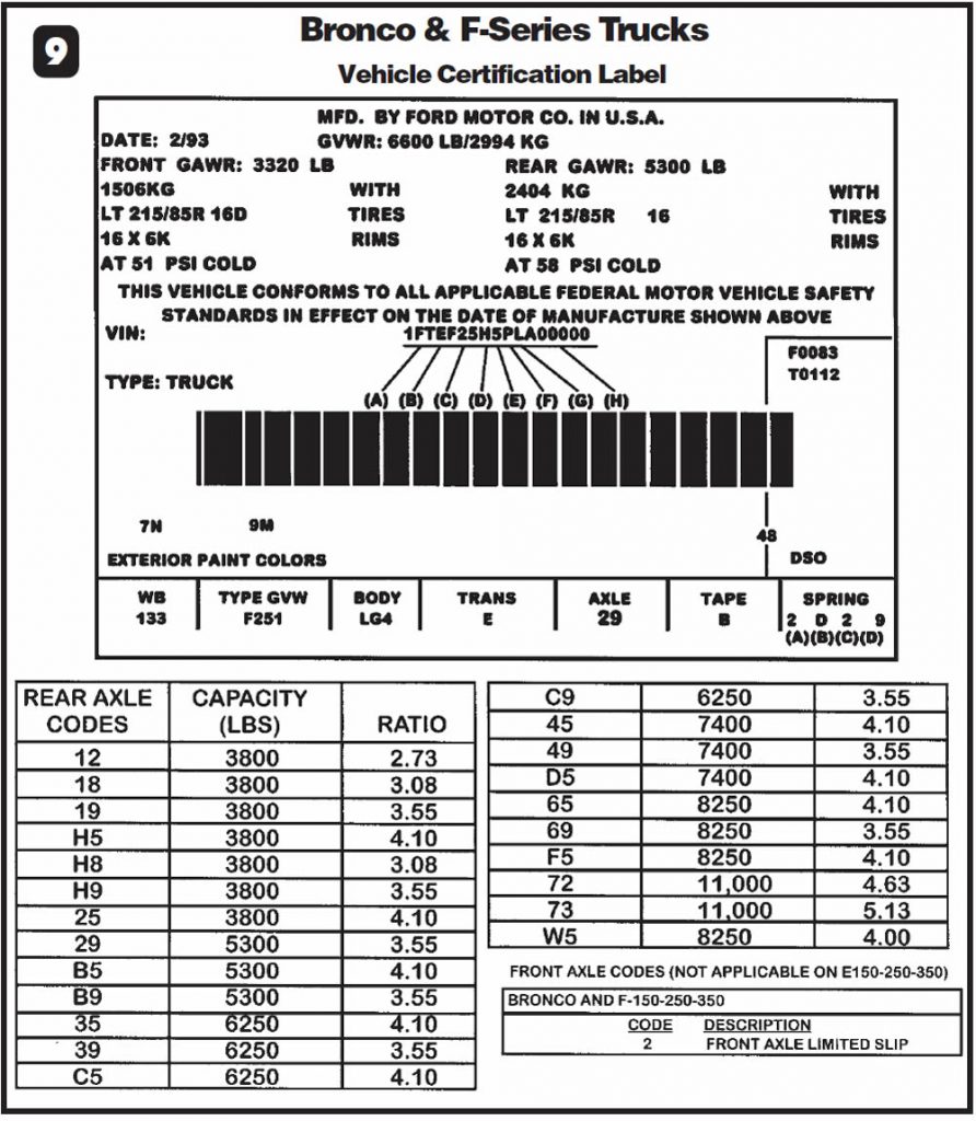
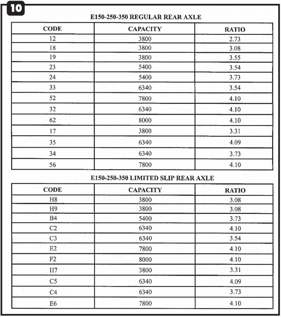
On the inside door jamb is the vehicle certification label, a sticker like the one shown at the top of Figure 9. Locate AXLE at the bottom of the sticker and read the code number below it. In Figure 9, the axle code is 29. In the chart at the bottom of Figure 9, you can see that axle code 29 signifies a 5,300-lb. capacity and a differential gear ratio of 3.55-1. Use the crossover charts in Figure 10 for all E-Series vans.
Step 2 – Exciter-Ring Tooth Count
The speed-sensor exciter ring is attached to the differential ring gear (see Figure 2). The only tooth counts available at the time of printing were 108 and 120. Removing the differential cover and counting the teeth is the only way to determine which exciter ring the vehicle has. In our example, the ring has 120 teeth.
Step 3 – Tire Size
You generally can find the tire size in one of two places: the tire sidewall or the vehicle certification label (refer to Figure 9). In Figure 9, the sticker shows a tire size of LT 215/85R 16D.
Step 4 – Calculating the Conversion Constant
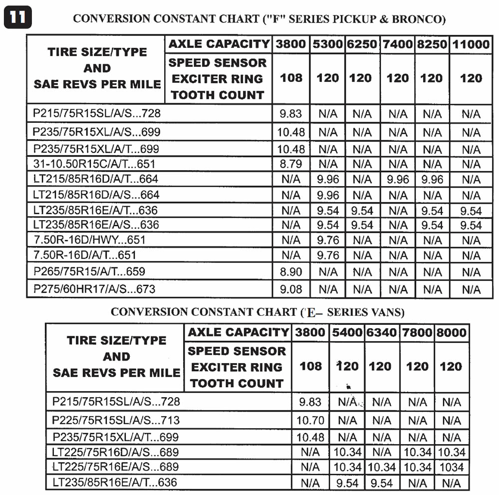
From the previous three steps, we have an F-Series truck with an axle capacity of 5,300 lbs., a speed-sensor exciter ring with 120 teeth and tire size of LT 215/85R 16D. Now look at the top part of Figure 11, which lists axle capacities, tooth counts and tire sizes for F-series pickups & Broncos. Directly below 5300, you’ll find the number 120, representing the 120-tooth speed-sensor exciter ring. Following this column down until it lines up with LT 215/85R 16D in the tire-size column to the left, you’ll find conversion constant 9.96. With this number, recalibration of the PSOM can begin.
Step 5 – Recalibrating the PSOM
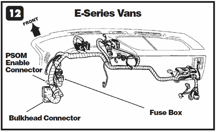
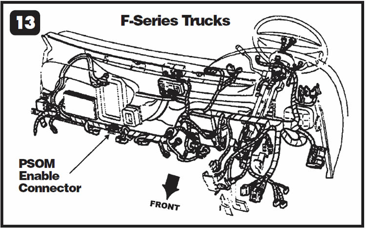
Locate the wire connector for enable circuit 567. This is a light-blue wire with a yellow tracer coming from pin 9 in the PSOM connector to a single connector. It is under the driver side of the dash below the fuse box near the bulkhead connector on E-Series vans (see Figure 12) and under the center of the dash below the glove box on F-Series trucks (see Figure 13).
Note:
The letters PSOM should be printed on the enable connector. Once you have found the connector, use the following procedures to reprogram the PSOM:
- With the ignition in the OFF position, ground the enable connector with a jumper wire.
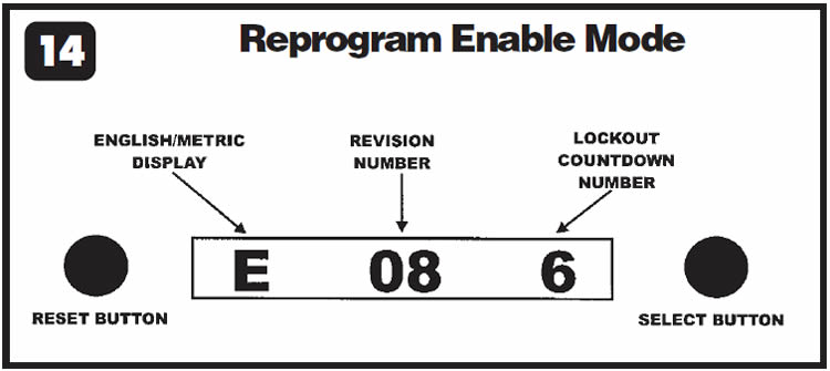
- While pushing in on the reset button of the trip odometer (see Figure 14), turn the ignition switch to the ON position. Do not start the engine. Once the switch is in the ON position, release the trip-odometer reset button.
- At this time the speedometer needle should sweep across the face of the speedometer and back again. This sweep indicates that the PSOM has been put into the enable mode. Looking into the LCD odometer window, you now should see the English/Metric display, the revision level number and the lockout count-down number, which indicates how many times the PSOM can be reprogrammed (see Figure 14).
Caution:
Each time the PSOM is recalibrated, the number of remaining times this can be done is reduced by one. PSOMs in 1992 vehicles can be recalibrated three times; those in 1993 and later vehicles can be recalibrated six times. If the count-down number is zero and the PSOM requires recalibration, the instrument cluster will require replacement.
Next, press the odometer reset button once more. Now you will see inside the odometer window the conversion-constant number without the decimal point, followed by the abbreviation CAL (see Figure 15).
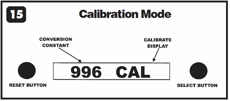
Next, press and release the select button as many times as necessary to change the conversion-constant number until you reach the desired number; in our example, 996. Each time you press the select button, the constant will decrease by one number. When you reach the desired constant number, press and release the reset button once to lock in the new conversion constant.
Turn the ignition OFF, remove the jumper wire from the PSOM enable connector and verify proper speedometer operation.

February 2002 Issue
Volume 19, No. 2
- Ford Trucks: Intermittent or Continuous Loss of Vehicle-Speed Signal


