
Technically Speaking
- Author: Wayne Colonna, Technical Editor
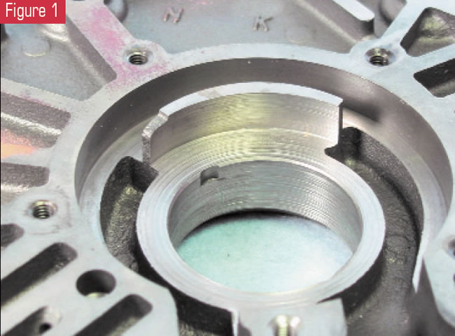
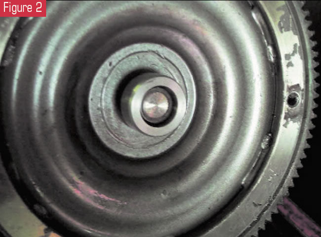
Have you ever encountered spin-out of the front pump bushing on a Mitsubishi KM unit as shown in Figure 1? Several years ago Paul Yaklin produced a bulletin explaining how the converter pilot bushing would get stuck on the pilot of the converter (see Figure 2). When the converter is removed, the pilot bushing stays with the converter unnoticed. Inevitably, a rebuilt converter then is installed without the adapter bushing in the crank bore. As a result, the centerline of the converter becomes seriously misaligned.
And to those of you who have not experienced this dilemma, you can only imagine the sinking feeling that occurs after you discover that the fluid is pouring out onto the floor as fast as it’s being poured in. The flex plate, pump and/or converter are some (if not all) of the parts that will need to be replaced.
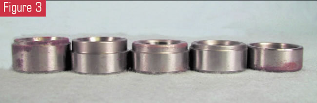
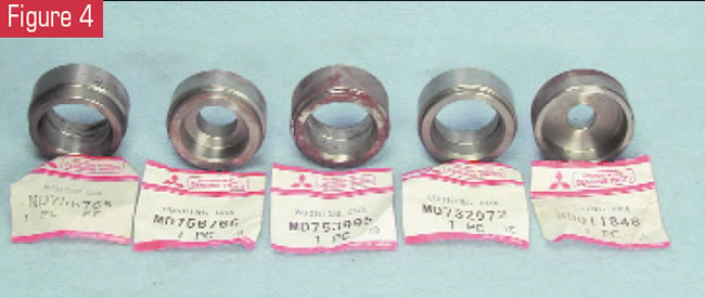
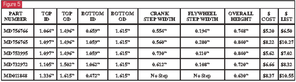
Don Stone from AAA Quality Transmissions in Stuart, Fla., has kept his eye on this potential problem in his shop, and through the years he has encountered five different sizes of adapter bushings (see Figure 3). He shared this information with us here at ATSG, and we are passing it on to you. Part numbers MD732972 and MD011848 seem to be used in 1992 and earlier, and the other three are used in the ’93 and later applications. You must be careful to select the proper bushing, since the overall height of the bushing varies, as well as a step on the flywheel side of the bushing (see Figure 4). The crankshaft diameters of these bushings are all the same. Figure 5 is a specification chart that matches up with part numbers to help you select the proper adapter bushing for your application.
A call came into the ATSG hotline recently from Andy Berry at Twin City Automatic Transmissions in Lancaster, N.Y., concerning an AX4S in a 1999 Windstar. The converter clutch would ramp up to about 50% then release harshly, followed by the tachometer and temperature gauge dropping out. In a relatively short time the gauges would return to normal operation and the whole process would repeat itself in a consistent, rhythmic manner.
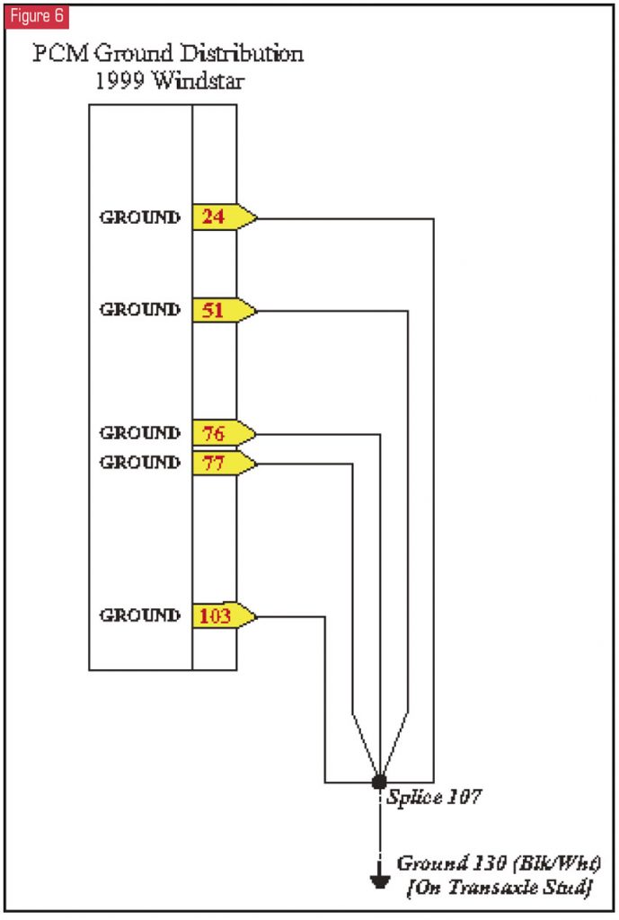
Whenever I receive a call like this I always go to checking grounds, and that is what we did. I sent Andy a wiring diagram noting that all the PCM ground wires merge and attach to a transaxle stud (see Figure 6). Well, it wasn’t long before Andy called back and said there were no ground wires on any part of his transaxle.
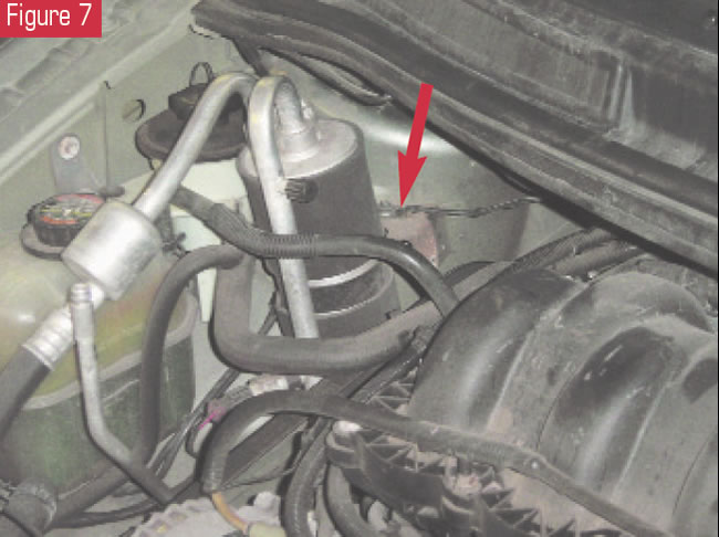
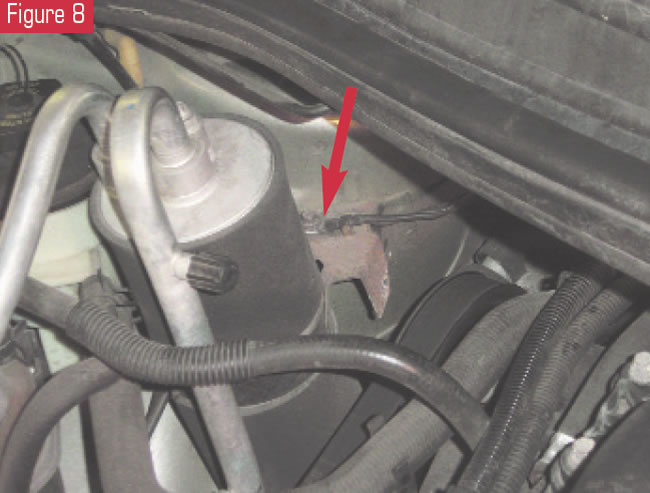
At that point the decision was made to go to the PCM and check the ground wires there. Well, Andy took it to the next level and traced the wires. What he found was that they all merged by the passenger-side shock tower. These wires were attached to an unpainted metal bracket for the AC receiver/dryer as shown in figures 7 and 8. What a place to put major ground wires! A little condensation makes for a little corrosion, and “ba-da-bing” – you have a computer going “kafluey.” After a good cleaning, all was well.
Another interesting call came in from Randy Walters at Wayne’s Car Care in Lynden, Wash. He was experiencing an unusual complaint of intermittent 3-2 downshifts with an RE4FO4A transaxle in a Nissan Quest (4F20E in a Villager).
Shift problems related to band apply are common on the hotline, and in most instances they are resolved by using an OEM-style band and making some valve-body modifications. Replacing the pilot-valve spring with one that has about 1.5-2 pounds more tension, adding a 700-R4 pressure-regulator-valve spring to the inside of the 1-2 accumulator spring, and installing two 125C front planetary shims on the stem side of the PR valve to increase spring tension are all you need to make a nice-shifting transmission in most instances.
Of course, the pressure-control solenoid and pump need to be in good working order. In Randy’s case, he had done these modifications yet still had intermittent 3-2 downshifts. He later called back after fixing the problem. What he found I will explain in steps.
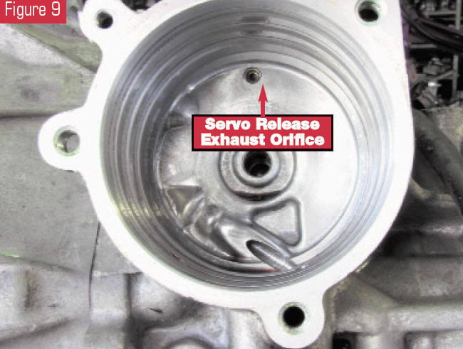
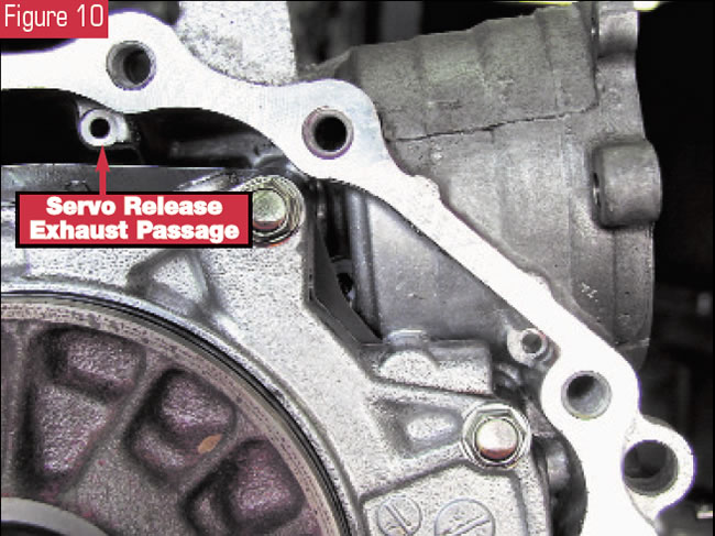
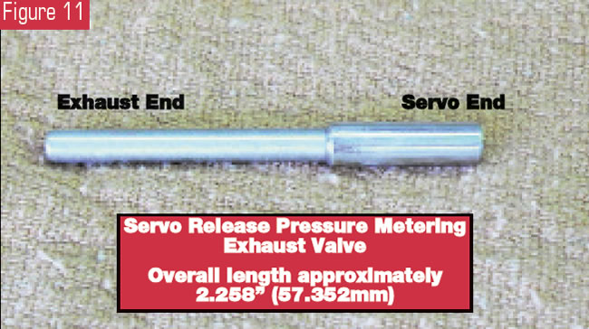
He removed the servo for inspection and found nothing unusual. He then looked into the servo bore and saw an orificed cup plug on the band-release side of the servo pocket (see Figure 9). He decided to blow air through it and found that it appeared to be blocked. He pulled the transmission, removed the cup plug and saw that there was a valve in the bore. He pulled the converter housing off, and an exhaust port leading to the back side of the valve bore became exposed (see Figure 10). It took several blasts of air from this port to get the valve out of the bore (see Figure 11). When it did come out, it shot out like a bullet. So if you should have to do this yourself, be sure that no one is in its way.
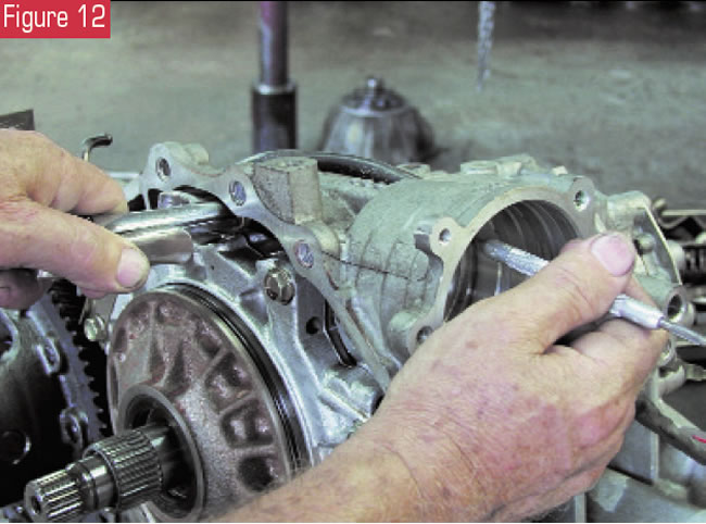
After cleaning out the bore and dressing the valve, he put it all back in place. He then checked the valve for movement by placing air pressure on the back side of the valve while moving it in and out with a pick from the servo-pocket side (see Figure 12). When the transmission was back in the car, it road-tested well.
The answer to this problem is that this stem valve is designed to provide a very small metered leak any time third-gear oil is present in the servo pocket. This prevents the release side of the servo from becoming air bound. When this circuit plugs up, air and residual oil fight band apply, causing frequent problems with the 3-2 downshift. Occasionally, the 1-2 upshift also is affected. It all depends on how fast you get from third down to first and back into second. If you are in first gear long enough, air and residual pressure may have enough time to dissipate sufficiently, allowing for a decent 1-2 upshift.
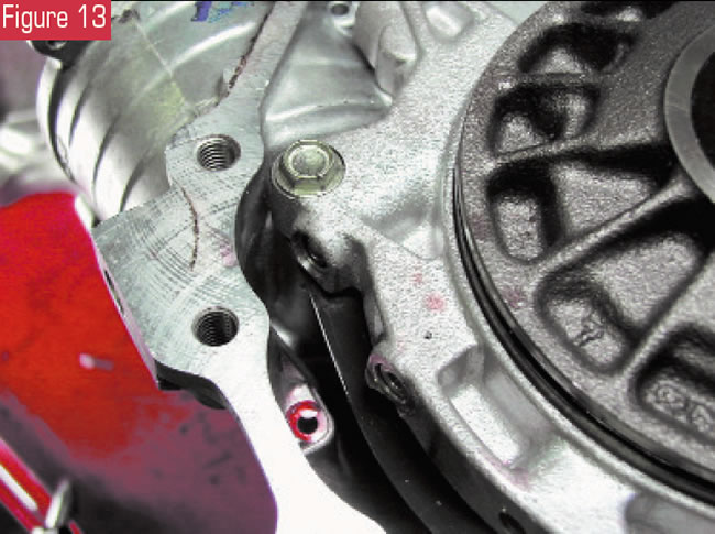
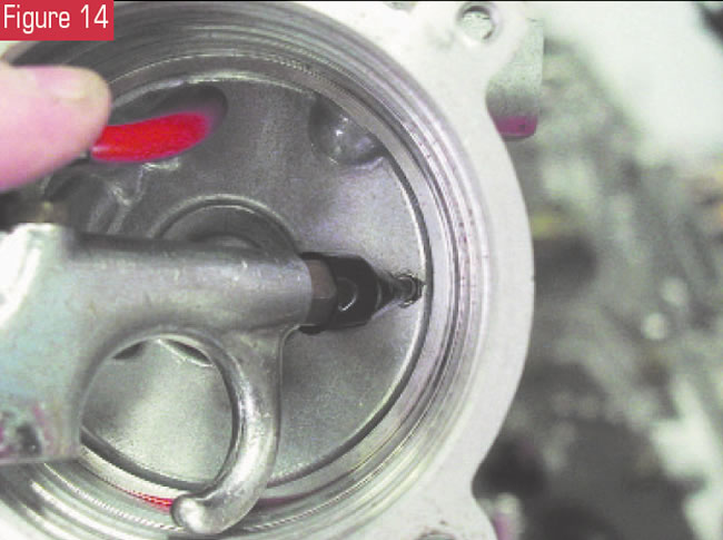
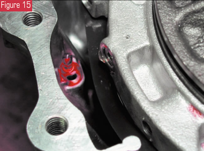
So the best way to check this valve while the unit is on the bench for repair is to fill as much fluid as possible into the exhaust side of the valve through the release port over the pump (see Figure 13). Blow compressed air through the orifice in the servo pocket as shown in Figure 14. The initial blast will push some fluid out (see Figure 15).
Maintain your supply of compressed air and watch for the residual fluid to hiss out. If it continues to hiss out, the circuit is good. If the hissing stops, try squirting additional fluid into the circuit while keeping air pressure on the servo side of the valve. If you can accomplish this task, the valve will need to be removed for cleaning, as the hissing of the fluid should remain continuous. The valve should not close off the bore.


