The GM 8L90 Stop/Start or Go/No-Go - Transmission Digest

The GM 8L90 Stop/Start or Go/No-Go

The Stop/Start feature many vehicles are equipped with today is in my opinion one of the most annoying features a vehicle could ever have. Of course, my opinion doesn’t reflect the opinion of others, but what is undeniably annoying is when the stop/start feature is not working correctly, especially when it is self-inflicted.

Take, for example, a GM 8L90 transmission. There is a valve body designed to be used in this transmission for vehicles that are equipped with this type of technology. The changes to the valve body are quite subtle and could be missed if one is not aware of them. So, if this style of valve body is used in a non-stop/start application, the transmission will appear to be working properly in a vehicle when it is up on the hoist; but once it is on the ground, it will barely move.

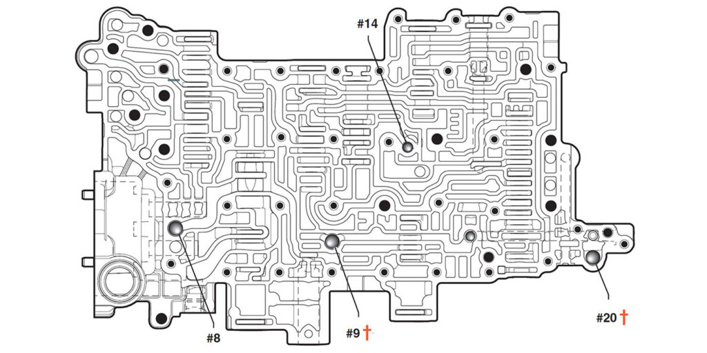
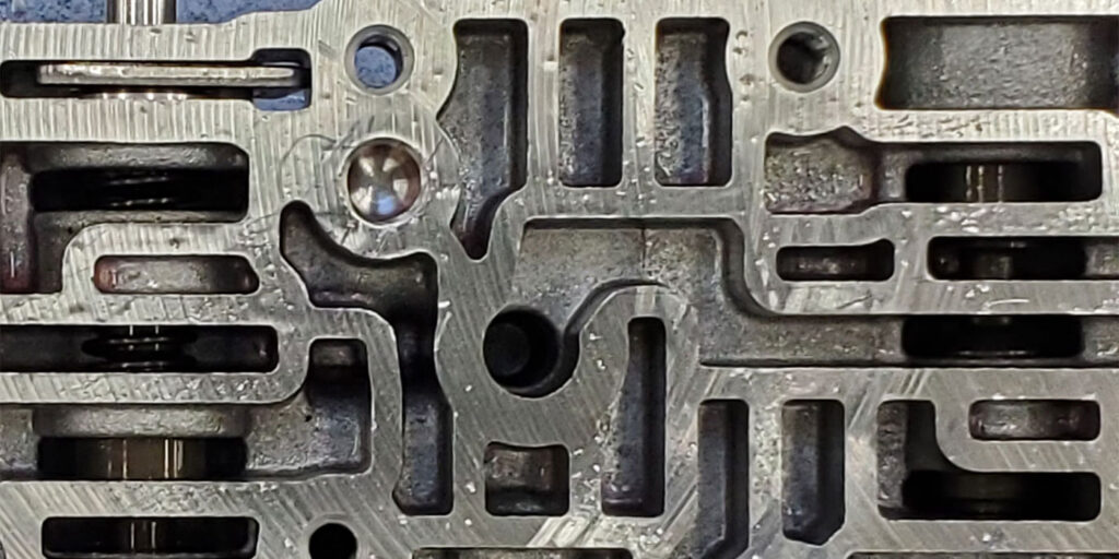
The stop/start valve body entails more than having two extra check balls (#3 and #20) as pointed out in Figure 1 to identify its difference.

Tech-Speak-November-Figure-1
Figure 1.

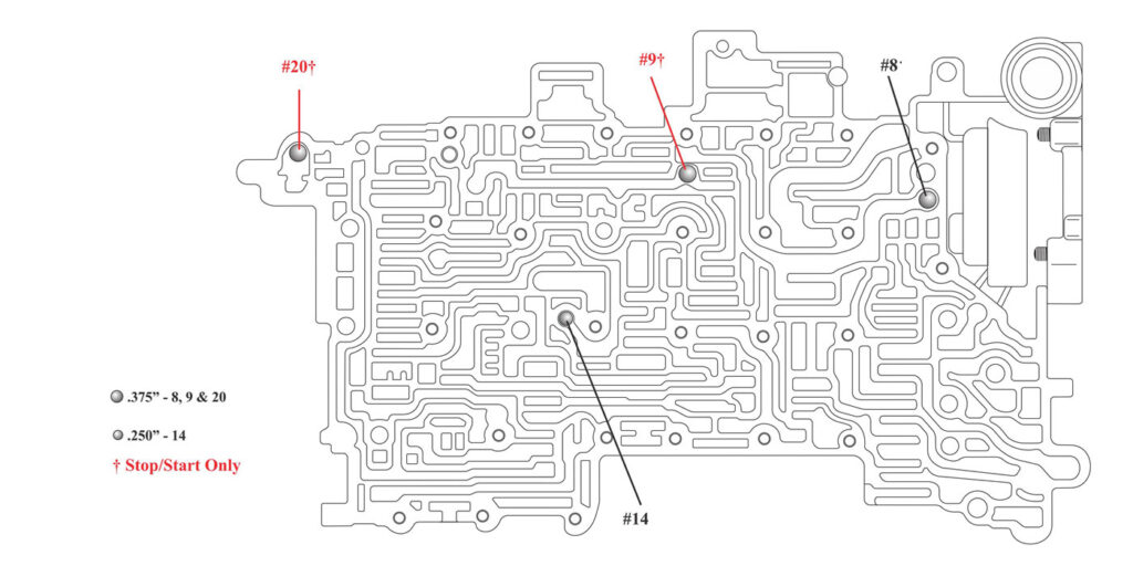
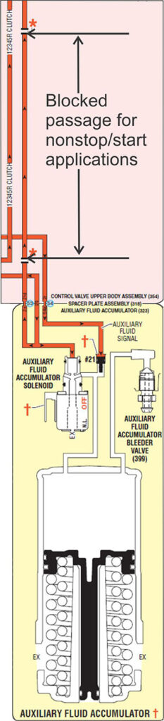
When you look at the check ball locations in GM’s Technician Guide (Figure 2), it points out the same two check balls as seen in Figure 1. But, notice that it has two passages in dotted lines associated with these two check balls.

Tech-Speak-November-Figure-2
Figure 2.

When you look in the hydraulics related to this circuit, it shows that these passages are blocked in non-stop/start applications (Figure 3). This means these two circuits are open and functional with a transmission that has this stop/start feature.

Tech-Speak-November-Figure-3
Figure 3.

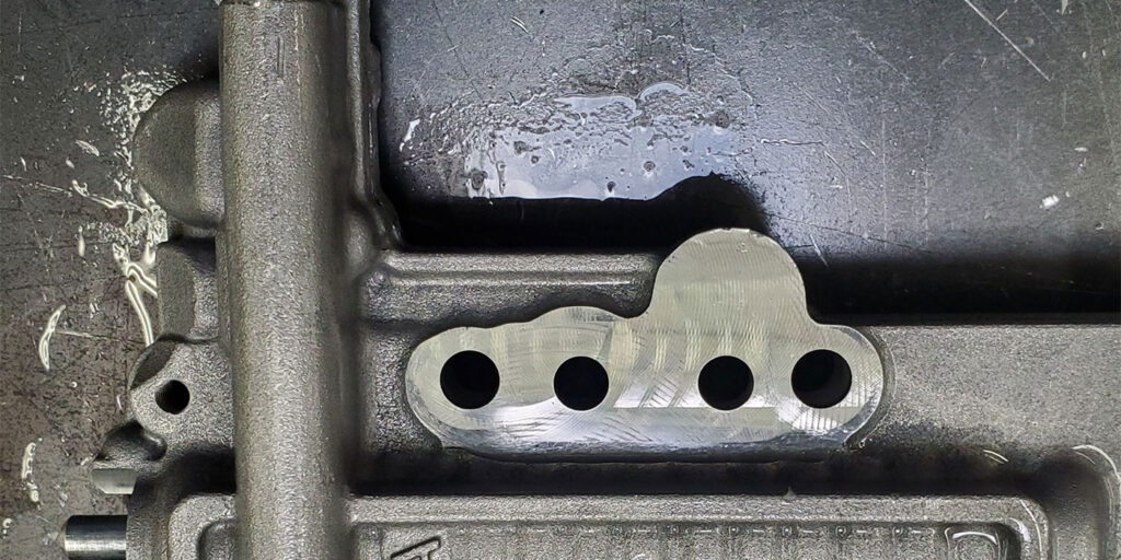
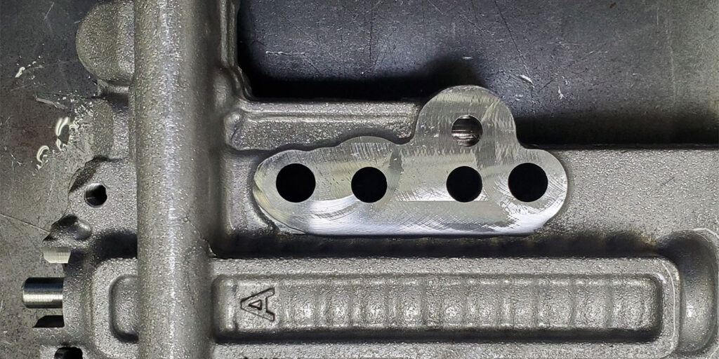
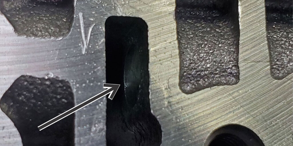
To see these subtle differences, Figure 4 shows the corner of a non-stop/start valve body, where the #20 check ball would be located on a vehicle with the stop/start feature.

Tech-Speak-November-Figure-4
Figure 4.

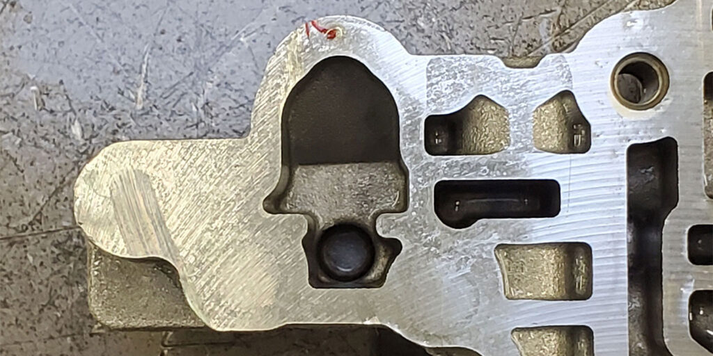
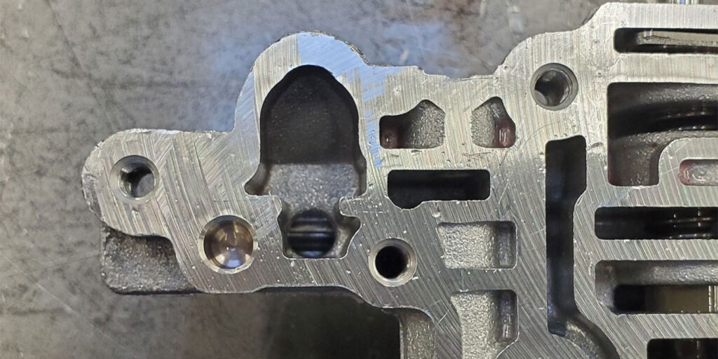
Figure 5 is a valve body with this feature. Just a cursory look in this area would cause one to easily overlook that the passage in Figure 4 is blocked while in Figure 5 it is open.

Tech-Speak-November-Figure-5
Figure 5.

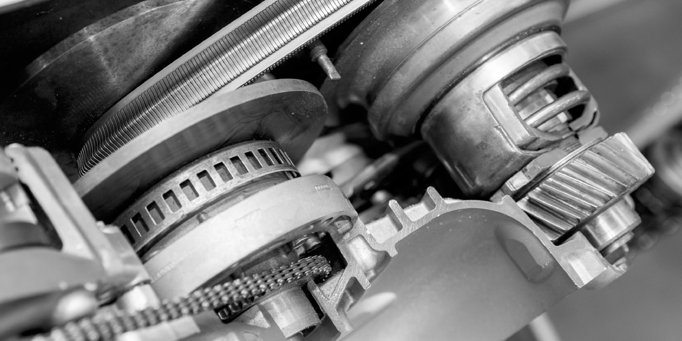
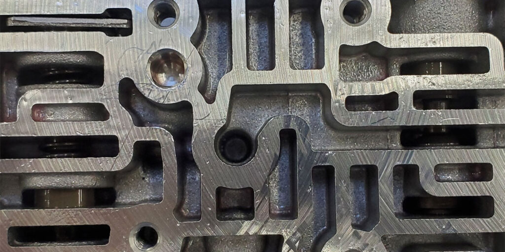
The same can be seen in the circuit going to the #9 check ball by comparing Figure 6 with Figure 7. Figure 6 shows the circuit being blocked, whereas Figure 7 shows it open. These circuits are like underground troughs formed into the casting of valve body.

Tech-Speak-November-Figure-6
Figure 6.
Tech-Speak-November-Figure-7
Figure 7.

One quick way to identify a stop/start valve body is by looking at the case side of the valve body. There will be an additional hole to supply pressure to the 12345R clutch from the auxiliary fluid accumulator assembly. Figure 8 shows a non-stop/start valve body, while Figure 9 shows the additional hole the stop/start valve body provides.

Tech-Speak-November-Figure-8
Figure 8.
Tech-Speak-November-Figure-9
Figure 9.

The way the case is designed with an elongated north/south rectangular feed passage means that it will accommodate both one-hole and two-hole valve bodies (Figure 10). This additional passage is routed towards the #20 check ball.

Tech-Speak-November-Figure-10
Figure 10.

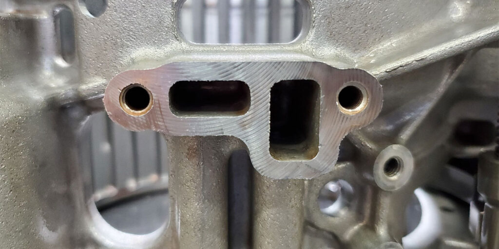
Figure 11 is an attempt to show how these passages are like underground troughs formed into the casting of valve body. A flashlight was placed onto the additional feed hole seen in Figure 9. Looking at Figure 11, an arrow is pointing at the opposite end of the passage where a little of the light is shinning through.

Tech-Speak-November-Figure-11
Figure 11.

Without knowing these little details, a stop/start valve body can be easily installed in a non-stop/start application. And this will be the difference between having a go or no-go transmission.

Keep in mind too that it’s just as easy to do the opposite. Installing a non-stop/start in a stop/start application will cause a delayed and abrupt engagement into gear after engine startup.

Each mistake makes for an annoying self-inflicted injury. Hopefully, this article will help prevent this from occurring for others.

Was this content valuable?

Thanks for your feedback!

You May Also Like

The importance of the follow-up road test after transmission replacement

A 2002 Lexus RX300 equipped with a 3.0-liter V6 engine and U140F transmission was brought into our facility with a few concerns. The customer said that “it has a leak, a grinding noise when taking off from a stop, and it just doesn’t seem to shift right.” They went on to tell us that this

RR Tech Feature Oct

A 2002 Lexus RX300 equipped with a 3.0-liter V6 engine and U140F transmission was brought into our facility with a few concerns. The customer said that “it has a leak, a grinding noise when taking off from a stop, and it just doesn’t seem to shift right.”

Tips and tricks for Chrysler switch valve plug testing

As technicians, we are often faced with build issues that can sometimes be frustrating at first. But with a little ingenuity, these frustrations can be turned around and made simple. Related Articles – GM 8L90 #7 Check-ball: The overheat that saved the day – ETE Reman: Ever expanding – Shift Pointers: Nissan’s no throttle response

tascfeature-1400
GM 8L90 #7 Check-ball: The overheat that saved the day

Beginning in October of 2015, GM removed the #7 Check-ball from the solenoid valve control body in the 8L90 transmission (see Figure 1). This was done in conjunction with the elimination of the Lube Override Enable Valve from the upper valve body as shown in Figure 2. Related Articles – Jatco/Nissan JF011E critical wear areas

Shift Pointers: Nissan’s no throttle response

Nissan vehicles using continuously variable transmissions (CVTs) are notorious for defaulting to a no throttle response when the vehicle is engaged into gear. There are several malfunctions that can cause this protective failsafe feature to be initiated. A brake switch (stop lamp switch) stuck on, a double-footed driver, blown or incorrect brake bulbs, and wheel

Jatco/Nissan JF011E critical wear areas and vacuum test locations

Sonnax has provided the following guide on critical wear areas and vacuum test locations for the Jatco/Nissan JF011E. Technicians working on these models should find this guide helpful. (Ed. Note: This is an extended version of the guide found in our September issue, with three additional pages). Related Articles – Podcast: Talking CVTs with Transtar,

Other Posts

Tips for success with the GM transmission fast learn process

This article is about failure, something we all experience from time to time. If you are attempting to perform a fast learn process on a GM eight-, nine-, or 10-speed transmission, you may have that temporary feeling of failure, as this process can bring on frustration quickly. Let’s talk about what the fast learn process

tascFeaturefast-1400
Shift pointers: Tricky sensor situations

Sometimes you’re the windshield and sometimes you’re the bug—a phrase many of us have heard and experienced. It’s inevitable. The idea is to be the windshield as much as possible. Shane from Cottman Transmissions had a helluva day but in the end, he was the windshield. Related Articles – CVT maintenance basics – Mercedes-Benz 722.9

Look for the little details: Three transmission repair case studies

Below are three examples of trucks that came into transmission shops, yet either did not have a transmission problem, or had a simpler issue than it originally seemed. Read on for the stories. Related Articles – Infiniti G37 RE7R01A chassis codes set – Honda Accord BB7A six-speed: P2720 code set after collision – Troubleshooting RFE

techspeakfeature-1400
CVT maintenance basics

On the maintenance side, a continuously variable transmission (CVT) requires more or the same frequency of fluid and filter changes as a conventional automatic transmission, and many of the basic procedures are the same. On the diagnostic side, a CVT transmission is less complicated internally than a six- or nine-speed transmission. Related Articles – The

CVT-Transmission