

Issue Summary:
- A Honda vehicle equipped with a BAXA/B7XA-family transmission exhibits flared or slipping upshifts before or after overhaul.
- A Mitsubishi or Hyundai vehicle with an F4A40/50-series transmission comes back after overhaul with the second-clutch plates burnt and code P0732 stored.
- Before or after overhaul, the malfunction indicator lamp (MIL) is illuminated on a Honda vehicle equipped with a BAXA/B7XA-family transmission and code P1705 is stored.


Before or after overhaul, a Honda vehicle equipped with a BAXA/B7XA-family transmission exhibits a complaint of flared or slipping upshifts. This could be a “cold-only” condition, or the problem may continue even after warm-up.

One cause may be a loss of clutch-apply pressure at the clutch-pressure-control (CPC) valves in the accumulator valve body. Loss of clutch-apply pressure can be caused by faulty CPC solenoids, a faulty clutch-pressure switch or a problem with the CPC valves in the valve body. The CPC valves are used to regulate clutch-apply oil during each gear-shift transition. The CPC valves are regulated by pressure from the CPC solenoids. The solenoids are activated and modulated by the ECM and use the clutch-pressure switches as an input for clutch-apply control.
The valves may stick in the bore during cold operation. If this happens, they cannot regulate clutch-control pressure adequately, causing a flared or sliding shift. The bore plugs that retain the CPC valves may become loose in the bore, or the bore in which the CPC valves travel may become worn and cause a loss of clutch-control pressure. This also can cause a flared or sliding shift.
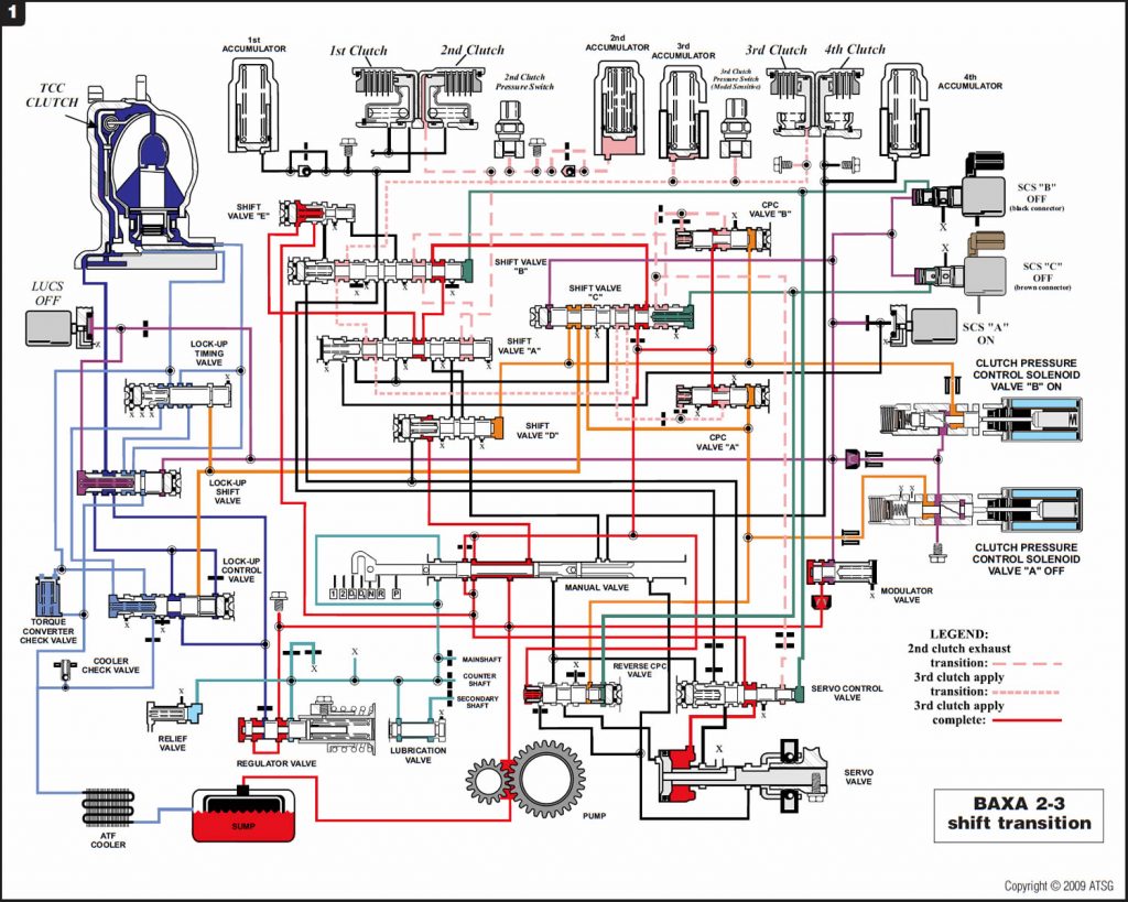
Refer to Figure 1 for a partial hydraulic diagram of the CPC system showing the transition between 2nd and 3rd gears.
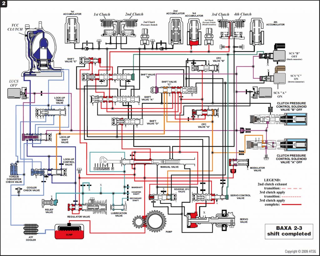
Refer to Figure 2 for a partial hydraulic diagram showing third gear fully applied.

When overhauling the transmission, you need to pay close attention to the CPC valves, the bore plugs and the CPC-valve bores in the accumulator body. There are several things that need to be done during the overhaul procedure to reduce the potential of having a repeat failure or continued problem.
The bores in the accumulator valve body where the CPC valves travel must be closely inspected for wear. If the bores are worn the accumulator valve body will need to be replaced.
Remove the CPC-valve springs from the body (leave the valves in and replace the bore plugs). Place the accumulator body in a freezer for at least two hours. After the body has had a chance to get good and cold, turn it from side to side and check whether the valves drag. The valves should float freely back and forth; if there is any drag, clean the bores with some very slightly abrasive cloth (be careful not to scratch the bore) or replace the accumulator body as necessary.
Make certain the bore plugs fit snugly in the bore. Use a tubing cutter around the outside of each plug to raise a ridge that will help the bore plugs fit much tighter and help reduce the possibility of leaking.
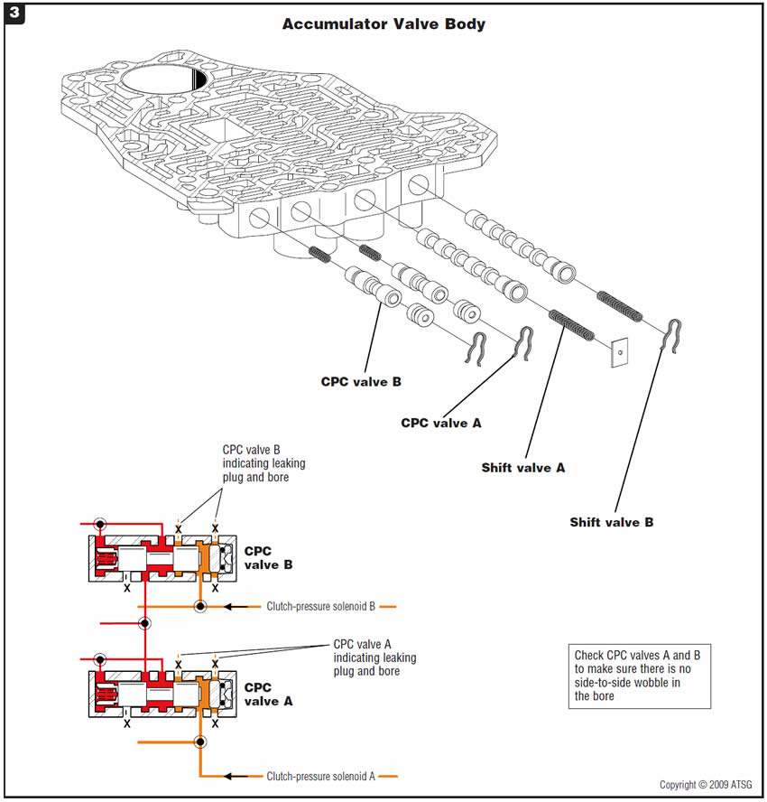
Refer to Figure 3 for a diagram of the accumulator valve body and CPC-valve locations.


The vehicle comes back after overhaul with the second-clutch plates burnt. Overall line rise is good, and the only code stored is a P0732 for a second-gear-ratio error.
A second-clutch housing seal of incorrect length was used, or the second-clutch housing seal has failed and is leaking.
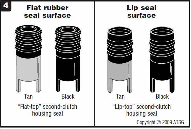
There are two different styles of rubber sealing methods for the second-clutch housing seal. One is referred to as a “lip-top” seal, and the other is referred to as a “flat-top” seal. The confusion arises because either type of seal could have either a tan or black base (Figure 4).
The reason is that these transmissions are found in vehicles from two different manufacturers: Mitsubishi and Hyundai. To add to the confusion, there are two different lengths, depending on whether the seal is to be used in an F4A42 or an F4A51. The F4A51 has a larger-diameter gearbox, making the distance between the valve-body surface of the case and the surface of the second-clutch housing shorter than that in the F4A42 transmission. Because of these differences, the shorter-length F4A51 seal could be used incorrectly in an F4A42 transmission, resulting in a loss of second-gear pressure because of compromised sealing ability of the second-clutch housing seal.
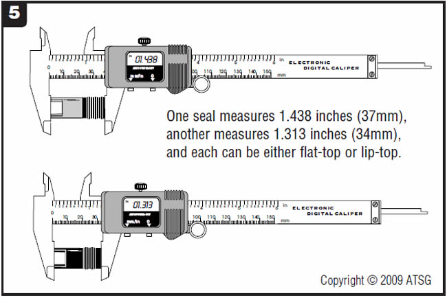
The F4A42’s second-clutch housing has an outside diameter of 6.813 inches (173.05mm) and a piston diameter of 6.625 inches (168.28mm). This requires a second-clutch housing seal 1.438 inches (37mm) long (Figure 5).
The F4A51’s second-clutch housing has an outside diameter of 7.625 inches (193.68mm) and a piston diameter of 7.500 inches (190.50mm). This requires a second-clutch housing seal 1.313 inches (34mm) long (Figure 5).
To ensure that the correct-length seal is used, perform the measurement shown in Figure 6. The measurement is taken from the valve-body surface of the case to the surface of the second-clutch housing. The F4A42 measurement will be 1.426 inches (36.22mm). The F4A51 measurement will be 1.305 inches
(33.15mm).
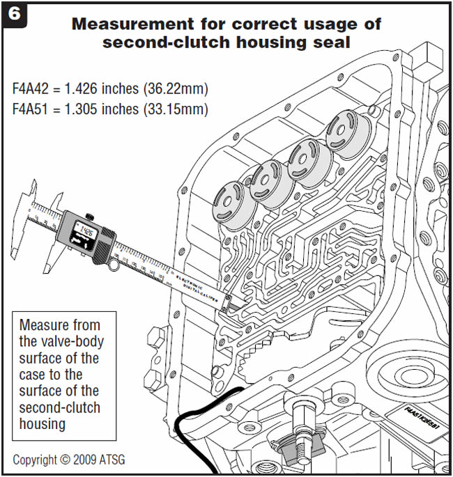
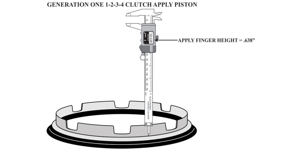
Note: Be careful when replacing the second-clutch piston; it comes in three different thicknesses.

Short seal
- Mitsubishi lip-top . . . . . . . . . . . . . . . . . . . . . . . . MD757210
- Hyundai flat-top. . . . . . . . . . . . . . . . . . . . . . . . 45675-39001
Long seal
- Mitsubishi lip-top . . . . . . . . . . . . . . . . . . . . . . . . MD757211
- Hyundai flat-top. . . . . . . . . . . . . . . . . . . . . . . . 45675-39501


Before or after overhaul, a Honda vehicle equipped with a BAXA/B7XA-family transmission exhibits a complaint of the malfunction indicator lamp (MIL) illuminated. When you check for codes, you detect DTC P1705.
One cause may be a problem with the powertrain control module (PGM-FI) main relay stuck closed.
To check for the PGM-FI main relay being stuck closed, have a suitable scan tool connected to the OBD-II connector under the driver side of the dash. Turn the ignition switch to the OFF position. If the scan tool does not lose communication, the PGM-FI main relay is stuck closed; proceed to Correction 1. If the scan tool does lose communication, the problem may be intermittent. Cycle the ignition several times with the scan tool still connected and see whether the code can be reproduced. If the scan tool loses communication and the code returns, proceed to Correction 2.
Correction 1:
Replace the PGM-FI main relay.
Correction 2:
To diagnose and check the A/T gear-position switch, go to A/T gear-position-switch test.
AT gear-position-switch test:
Turn the ignition switch to the ON position. Move the gear selector from the Park position down each detent to the D1 position. Check to see whether the gear-position indicator light illuminates for each position. If any indicators stay illuminated in a position that is not indicated by the gear selector, proceed with the gear-position-switch test. If indicators illuminate correctly, the problem may be intermittent; wiggle the harness and repeat the test.
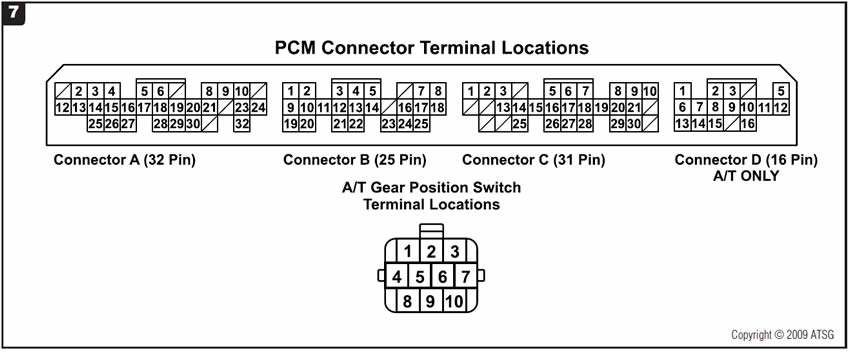
Pull the carpet back from both passenger and driver sides of the vehicle and locate the PCM behind the center console. There will be four connectors at the PCM: connector A (32-pin), connector B (25-pin), connector C (31-pin) and connector D (16-pin). Refer to Figure 7 for identification of the PCM connector pins and the A/T gear-position-switch pins.
Refer to Figure 8 for a partial wiring diagram of A/T gear-position switch.
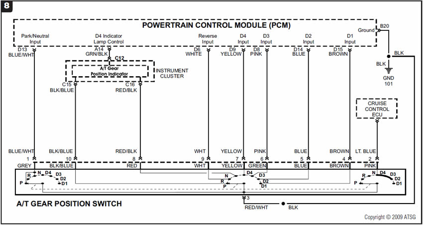
Note: Pin locations and wire colors are specifically for 1998-99 Honda Accords with four-cylinder engines. Locations and colors on other models may vary.
Preliminary:
Preliminary checks for integrity of ground wire B20 at the PCM-harness connector.
Using a DVOM set to read DC volts, back-probe terminal B20 (brown/black wire) with the red lead of the meter. Place the black lead of the meter to the battery negative terminal. The meter should indicate a reading of 0.1 volt or less with the ignition on. If OK, proceed. If not OK, repair ground circuit B20.
Step 1:
Step 1 checks the integrity of the park/neutral input.
Using a DVOM set to read DC volts, back-probe terminal B20 (brown/black wire) with the black lead of the meter and probe terminal D13 (blue/white wire) with the red lead. Turn the ignition switch to ON and check for voltage. Move the gear selector slowly through each range. The meter should indicate a voltage reading of 0.1 volt or less in park and neutral. All other gear ranges should indicate about 5 volts. If OK, proceed to Step 2. If you see voltage in park/neutral, disconnect the connector at the gear-select switch on the transmission and check for continuity between terminal D13 at the PCM and terminal 1 at the gear-position switch. If no continuity exists, repair the open in the circuit. If continuity is good, replace the gear-position switch. If you observe less than 0.1 volt in all positions, disconnect both connectors and check for continuity between terminal D13 at the PCM and ground. If continuity exists, repair the short to ground in the circuit. If no continuity exists, the PCM is at fault.
Step 2:
Step 2 checks integrity of reverse input.
Using a DVOM set to read DC volts, back-probe terminal B20 (brown/black wire) with the black lead of the meter and probe terminal D6 (white wire) with the red lead. Turn the ignition switch to ON and check for voltage. Move the gear selector slowly through each range. The meter should indicate a voltage reading of 0.1 volt or less in reverse. All other gear ranges should indicate about 12 volts. If OK, proceed to Step 3. If you see voltage in reverse, disconnect the connector at the gear-select switch on the transmission and check for continuity between terminal D6 at the PCM and terminal 9 at the gear-position switch. If no continuity exists, repair the open in the circuit. If continuity is good, replace the gear-position switch. If you observe less than 0.1 volt in all positions, disconnect both connectors and check for continuity between terminal D6 at the PCM and ground. If continuity exists, repair the short to ground in the circuit. If no continuity exists, the PCM is at fault.
Step 3:
Step 3 checks the integrity of the D4 input.
Using a DVOM set to read DC volts, back-probe terminal B20 (brown/black wire) with the black lead of the meter and probe terminal D9 (yellow wire) with the red lead. Turn the ignition switch to ON and check for voltage. Move the gear selector slowly through each range. The meter should indicate a voltage reading of 0.1 volt or less in D4. All other gear ranges should indicate about 5 volts. If OK, proceed to Step 4. If you see voltage in D4, disconnect the connector at the gear-select switch on the transmission and check for continuity between terminal D9 at the PCM and terminal 7 at the gear-position switch. If no continuity exists, repair the open in the circuit. If continuity is good, replace the gear-position switch. If you observe less than 0.1 volt in all positions, disconnect both connectors and check for continuity between terminal D9 at the PCM and ground. If continuity exists, repair the short to ground in the circuit. If no continuity exists, the PCM is at fault.
Step 4:
Step 4 checks the integrity of the D3 input.
Using a DVOM set to read DC volts, back-probe terminal B20 (brown/black wire) with the black lead of the meter and probe terminal D8 (pink wire) with the red lead. Turn the ignition switch to ON and check for voltage. Move the gear selector slowly through each range. The meter should indicate a voltage reading of 0.1 volt or less in D3. All other gear ranges should indicate about 12 volts. If OK, proceed to Step 5. If you see voltage in D3, disconnect the connector at the gear-select switch on the transmission and check for continuity between terminal D8 at the PCM and terminal 6 at the gear-position switch. If no continuity exists, repair the open in the circuit. If continuity is good, replace the gear-position switch. If you observe less than 0.1 volt in all positions, disconnect both connectors and check for continuity between terminal D8 at the PCM and ground. If continuity exists, repair the short to ground in the circuit. If no continuity exists, the PCM is at fault.
Step 5:
Step 5 checks the integrity of the D2 input.
Using a DVOM set to read DC volts, back-probe terminal B20 (brown/black wire) with the black lead of the meter and probe terminal D14 (blue wire) with the red lead. Turn the ignition switch to ON and check for voltage. Move the gear selector slowly through each range. The meter should indicate a voltage reading of 0.1 volt or less in D2. All other gear ranges should indicate about 12 volts. If OK, proceed to Step 6. If you see voltage in D2, disconnect the connector at the gear-select switch on the transmission and check for continuity between terminal D14 at the PCM and terminal 5 at the gear-position switch. If no continuity exists, repair the open in the circuit. If continuity is good, replace the gear-position switch. If you observe less than 0.1 volt in all positions, disconnect both connectors and check for continuity between terminal D14 at the PCM and ground. If continuity exists, repair the short to ground in the circuit. If no continuity exists, the PCM is at fault.
Step 6:
Step 6 checks the integrity of the D1 input.
Using a DVOM set to read DC volts, back-probe terminal B20 (brown/black wire) with the black lead of the meter and probe terminal D15 (brown wire) with the red lead. Turn the ignition switch to ON and check for voltage. Move the gear selector slowly through each range. The meter should indicate a voltage reading of 0.1 volt or less in D1. All other gear ranges should indicate about 12 volts. If OK, refer back to PGM-FI relay test with scan tool. If you see voltage in D1, disconnect the connector at the gear-select switch on the transmission and check for continuity between terminal D15 at the PCM and terminal 4 at the gear-position switch. If no continuity exists, repair the open in the circuit. If continuity is good, replace the gear-position switch. If you observe less than 0.1 volt in all positions, disconnect both connectors and check for continuity between terminal D15 at the PCM and ground. If continuity exists, repair the short to ground in the circuit. If no continuity exists, the PCM is at fault.
- PGM-FI main relay (two-door models). . . Honda part # 39400-582-A01
- PGM-FI main relay (four-door models). . . Honda part # 39400-584-003
- A/T gear-position switch . . . . Honda part # 28900-P6H-013

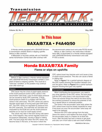
May 2009 Issue
Volume 26, No. 5
- Honda BAXA/B7XA Family: Flares or slips on upshifts
- Honda BAXA/B7XA Family: Flares or slips on upshifts
- Honda BAXA/B7XA Family: MIL Illuminated, Setting DTC P1705