Shift Pointers
- Author: Wayne Colonna, Technical Editor
Assembly Procedure for Low/Reverse, Second-Brake Clutch Packs
Misassembly of the low/reverse and/or second-brake clutch packs in Mitsubishi’s F4A40 and 50 series transaxles can occur easily. Especially if you are the individual who answers phones, makes parts orders, road-tests vehicles, handles problems under the lift and rebuilds transmissions, all in a day’s work. And when a misassembly takes place, the transmission may slip through second, chatter in reverse, go to limp mode with a second-gear ratio code and/or a solenoid-performance code.
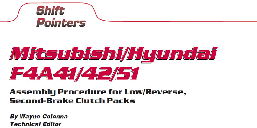
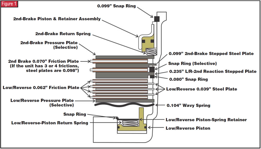
The stack-up in itself is a little tricky to start with, but with the quantity of steel and friction plates varying depending on car model and engine application, odds for misassembly increase. To help make this as easy as possible for you, Figure 1 provides a cross-sectional view of the entire two clutch-pack stack-ups identifying the order of each item in the assemblies. You could copy and pin this on the wall in your shop. The chart in Figure 2, which gives you the correct quantity of friction and steel plates used in the various transmission models, also can be copied and put up on your wall.
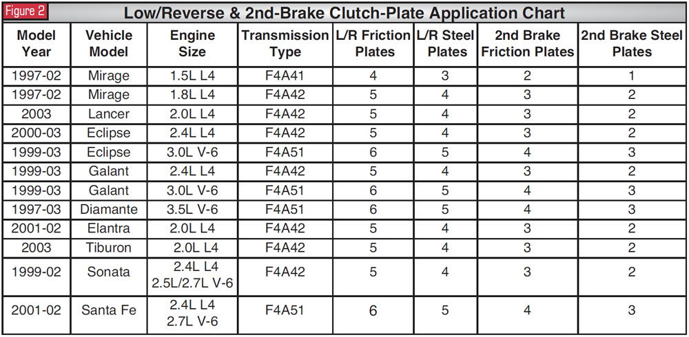
Clutch-pack clearance for the low/reverse clutch is 0.048-0.062 inch. The second-brake clearance is 0.025-0.040 inch. The chart in Figure 3 provides the correct selective snap ring to adjust the height of the second-brake stepped reaction plate, and charts in figures 4 and 5 provide information on the selective pressure plates for adjusting both clutch packs.
There is a low/reverse and 2nd-clutch “dummy plate” adjustment tool used to obtain proper clutch clearance during transmission assembly. In the event you wish to fabricate one, the tool’s specifications for the F4A41/42 are 6.25 inches O/D, 0.075 inch thick, and specifications for the F4A51 are 7.16 inches O/D, 0.075 inch thick. However, a feeler gauge will work equally as well, as long as you take care not to damage the friction plates. If you like to buy tools, the part number for the F4A41/42 dummy plate is MB991631-01. For the F4A51, the part number is MB991632-01.
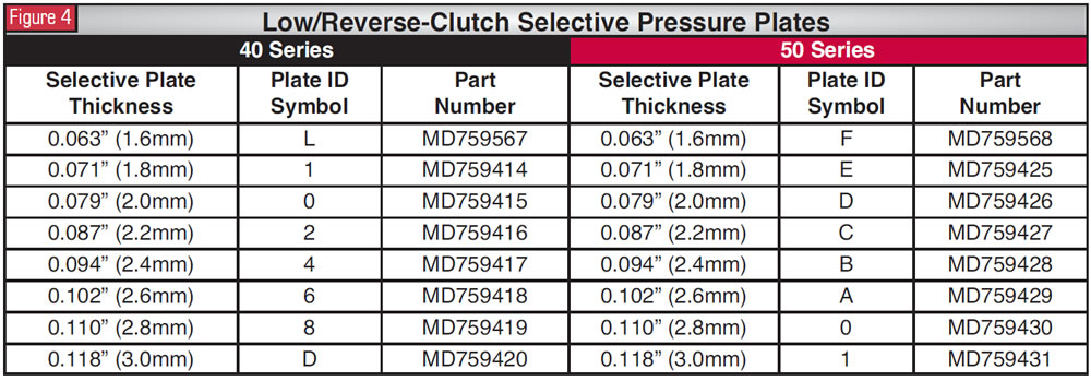
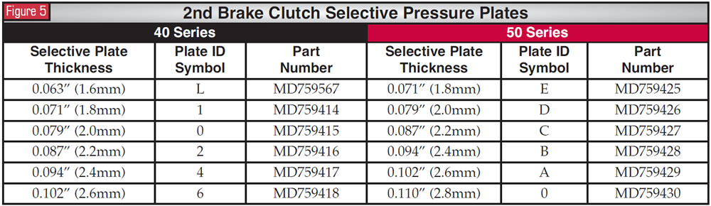
So, let’s get started. After the low/reverse piston has been installed, the first item to go in is the 0.104-inch wavy spring (see Figure 6). After the wavy spring come the proper number of low/reverse steel and friction plates, with the selective pressure plate at the bottom to go against the 0.104-inch wavy spring (see Figure 7).
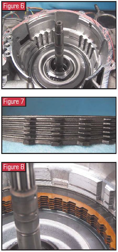
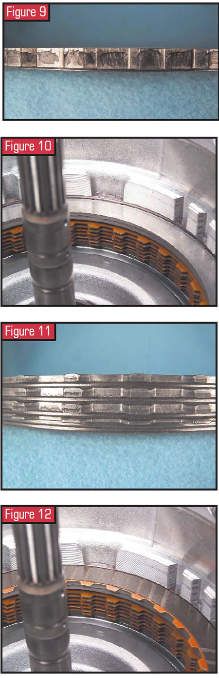
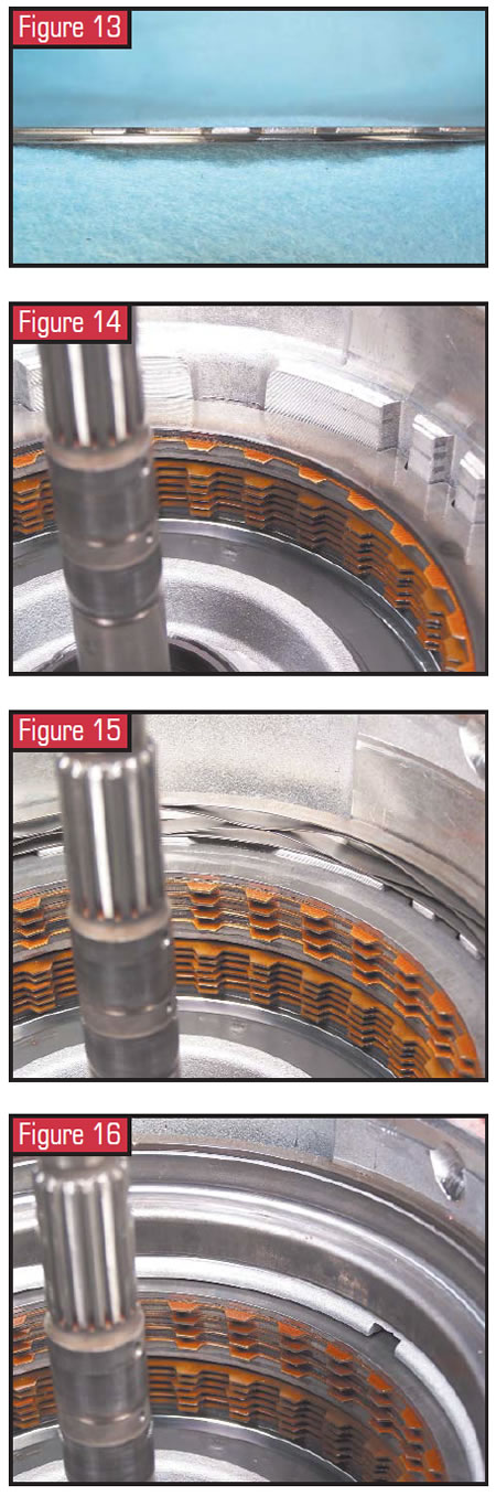
You can see in Figure 1 that the L/R steel plates are 0.039 inch thick and the friction plates are 0.062 inch. Once the L/R pack is in place an 0.080-inch snap ring goes in (see Figure 8), then the 0.235-inch L/R-2nd reaction plate with the step side facing down (see Figure 9). Then comes the selective snap ring (see Figure 10), followed by the 2nd-brake stack-up (see Figure 11). Place a friction down into the transmission first (see Figure 12), then the stepped plate (see figures 13 and 14) followed by the rest of the stack-up, ending with the selective pressure plate (see Figure 15). The 2nd-brake accordion return spring then is placed on top of the pressure plate (see Figure 16). Now the 2nd-brake piston and retainer assembly can be installed and secured with a 0.099-inch retaining snap ring (see Figure 17).
One extra note: The quantity of frictions is determined by the heights of the pistons. Other dimensional differences to watch for occur between low-sprag and non-low-sprag units.


