A 2001 Chevrolet S-10 pickup came into our shop the other day. This job started with a concern of the engine revving high and not shifting correctly. With the truck being equipped with a 4L60E transmission, I expected to find non-functioning third and fourth gears, which is a common failure for these transmissions.
I scanned for codes and found P0758 (2-3 shift solenoid B circuit fault) stored. Next, I was off on a road test with my scanner set to monitor the commanded shift, gear ratio SSA (shift solenoid ‘A’), and SSB (shift solenoid ‘B’) status. Starting out in first gear felt normal, second was good also, but when the scanner showed the command for third gear, I didn’t feel any shift and the engine RPM continued to climb. The gear ratio showed 1.6:1 (second gear). Continuing to slowly increase speed, the scan data showed fourth gear commanded with no drop in RPM and still at the 1.6:1 gear ratio. Continuing down the street holding the throttle steady, suddenly the engine speed dropped, and gear ratio was then at .69:1 (fourth gear ratio).
With this being an unusual scenario, I chose to go to a quiet street where I can usually do several stop-and-go and slow maneuvers without encountering traffic. Again, from a stop and light throttle the 1-2 shift was nice and when the scanner showed third gear, the ratio stayed at 1.6:1. But this time I held the throttle and road speed steady, so the commanded gear remained in third.
Before I got to the end of the block, I felt a shift and the gear ratio then displayed 1.0:1 (third gear) with light acceleration; until fourth gear was commanded the transmission shifted nicely. Starting out from a stop in manual third gear, the shift feel and ratio change was delayed from the command by 20 to 25 seconds. Starting out in manual second and shifting to third when up to speed, the ratio change had the same delay. This continued throughout the road test starting with a cold transmission up to full running temperature.
Read more stories in our R&R Tech series here.
Back at the shop, I finished the preliminary checks of fluid level and condition, drive line condition and wire harness routing. With the scanner still connected, I decided to command the shift solenoids on and off and listen for the click of them turning on. When commanding SSA on and off I got a distinct “click clack” of the solenoid operation, but when commanding SSB I got a nice click but no clack. When turned off then commanded back on, there was no second click.
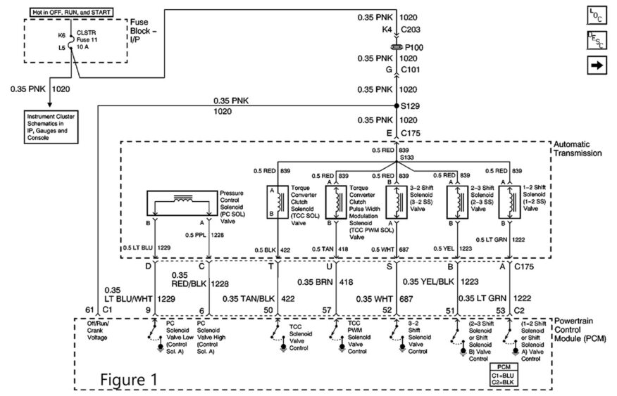
The first thing I wanted to do was look through service information and get the electrical schematic for the shift solenoids to confirm how they were powered and controlled, and what connector pins I would want to look at for testing. (See Figure 1, above).
A look through the diagnosis charts revealed the solenoid resistance specifications of 19-31Ω, and had a link to a nice chart of the shift solenoid valve states and gear ratios. (See Figure 2).
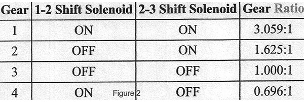
A quick study of the solenoid state chart confirmed that I wanted to look for a condition keeping the 2-3 solenoid on when commanded off; possibly a short to ground? The consistent replication of the symptoms made that seem unlikely. To begin testing, I needed to check the integrity of the circuits and solenoids.
Confirming that both solenoids used the same power source from the cluster fuse directly to the transmission and low side drivers in the PCM, I decided to test the entire circuit at the PCM connector. After disconnecting PCM connector C2 and locating terminals 51 and 52, I connected a battery maintainer to keep a constant battery voltage during testing. With the key on and engine off, I checked for battery voltage on each of the solenoid circuits and had 13V that matched the battery voltage. Keep in mind that at this point the circuit has no load on it, so finding full voltage only confirms a complete circuit and won’t show resistance issues.
Next, I checked the circuit resistance. When disconnecting just one connector that opens only one side of the circuit, I find it easier to test the current of the circuit with an ammeter inline of the terminal to ground. In this situation I decided to include a remote starter button in the meter to ground circuit.
Although I was looking for a fault in the 2-3 solenoid circuit, I first powered up the 1-2 control to get a comparison. With a reading of .49 amps and applying Ohm’s Law, the circuit resistance calculated to 26.5Ω, which was well within the solenoid specification. Using the remote button to turn the circuit on and off, I could hear the expected “click clack” of the solenoid. Doing the same test on the 2-3 control circuit had 27Ω resistance, and when using the remote button, the expected click clack of the solenoid was there and repeatable (remember, the turn off clack was missing when using the scanner command to cycle the 2-3 solenoid).
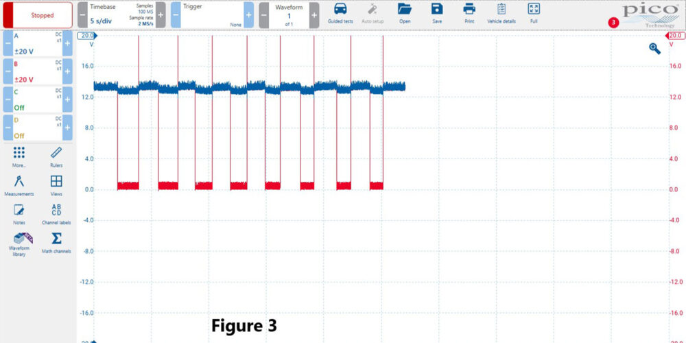
With a static and dynamic test of the solenoid and circuit all testing good, I reconnected the PCM connector, installed back probes into the control circuits, and connected a lab scope to capture the voltage when commanded through the PCM. The scope is connected to the low side driver circuit, and when the driver is commanded off, the circuit is open and should have source voltage. When turned on, it should be pulled low (0V).
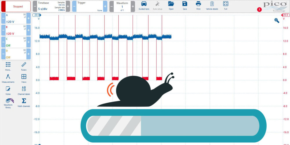
When commanding the 1-2 solenoid on and off with the scanner, it showed the circuit cycling from 13V to 0V with a crisp on/off line. The red trace is 1-2 solenoid and blue trace is 2-3 solenoid. (See Figure 3).
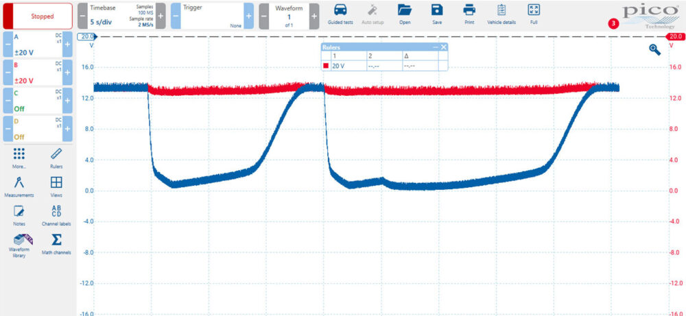
When commanding the 2-3 solenoid on and off with the scanner, it showed the circuit cycling from 13V to 0V; but the on/off time was slow to respond, with the off time taking 15 to 27 seconds. This corresponds with the delayed shift time that I experienced on the initial test drive. (See Figure 4).
I now felt that I had enough information to condemn the 2-3 solenoid driver as the fault, and to decide that PCM replacement would correct the problem. Once a replacement PCM was approved by the owner, it was installed and programmed. A nice “click/clack” could be heard from the 2-3 solenoid when commanded and a thorough road test confirmed a successful fix. Although I have worked with more of these trucks than I can remember, I had never seen this exact scenario; bad drivers usually were stuck on or off, not slow to respond as was the case here.
Starting with the necessary information, understanding the operation of the circuit, and using the proper diagnostic tools were all necessary for a thorough diagnosis and successful repair. This is the formula for a successful diagnosis no matter if we have been doing this for 30 years, or are just starting out.
Gordon Kehler started working as an auto mechanic in 1975, achieved his ASE Master certification in 1985, L1 in 1994, and both are kept current to date. He held GM master tech certification from 1991 to 2019. He joined the Certified Transmission team in 2019 as a diagnostician. He and his wife of 40 years have raised three children and have six grandchildren.