Technically Speaking
- Author: Wayne Colonna, Technical Editor
Powertrain Operation in Honda’s Hybrid-Electric Vehicles
A parallel hybrid vehicle allows the power from a gasoline engine and an electric motor to drive the vehicle independently or in conjunction with one another. The Toyota Prius has such a design as well as the Honda Insight and the Civic Hybrid. Although they are all parallel hybrids, there are differing operational strategies between Toyota and Honda.
The primary difference technically is the way in which they draw power from the electrical portion of the powertrain. At times both cars will use the gas and electric power sources together, splitting the total power supply to the wheels. In some situations the Toyota Prius will use only the electrical power to drive the wheels; Honda’s hybrids sometimes use only the power from the gasoline engine to drive the car.
The Toyota Prius uses a four-cylinder gasoline engine, and electrical power comes from the sealed nickel metal hydride (Ni-MH) battery. The battery supplies power to and is charged by a compound planetary gearset, which acts as a power-split device, through two motor generators inside the P111 transaxle. This design is simply called the Toyota Hybrid System (THS).
The Insight was Honda’s first hybrid to leave tread on the road in the year 2000. Its three-cylinder, 1.0-liter gasoline engine, called the ECA1, is a single-overhead-cam VTEC 12-valve design with sequential multiport fuel injection. The transmission in the first Insight was an SHR five-speed manual. The 2001 model offered the option of a continuously variable transmission (CVT), similar to the type of transmission used in the 1996-99 Honda Civic HX. The CVT in the ’96-99 HX is the M4VA, and in the Insight it is the MHTA.
For the 2003 model year, Honda replaced the Insight with the Civic Hybrid, which uses a four-cylinder 1.3-liter engine (LDA1) and offers a choice of the SZB five-speed manual transmission or the SZCA CVT.
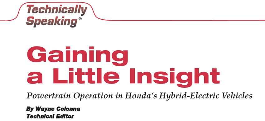
Unlike the Prius, Honda uses only one motor generator, which is mounted on the back of the engine behind the flywheel (see Figure 1). The motor is of a DC brushless design, meaning that it does not have carbon-tip contact points on the rotating center rotor. Although the design of the motor is DC brushless, it is a synchronous AC-type motor that serves three functions: It converts kinetic energy into electrical energy, assists the engine during acceleration and starts the engine. This is Honda’s Integrated Motor Assist (IMA) hybrid design.
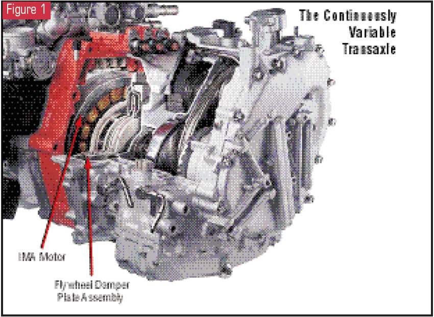
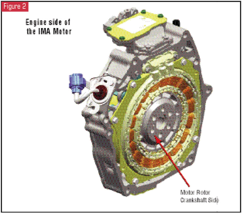
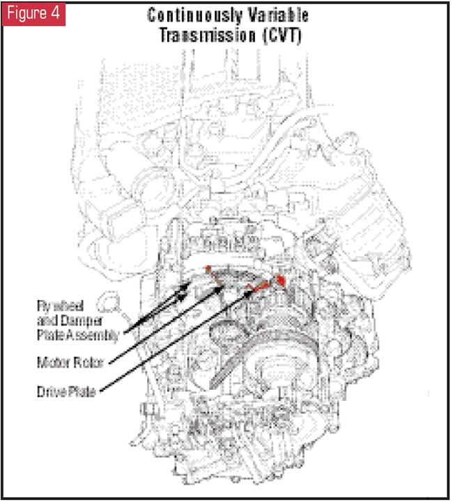
Figure 2 shows the engine side of the IMA motor. In the center is the motor rotor that bolts up to the engine crankshaft. On the transmission side of this motor rotor, the flywheel or drive plate is attached to accommodate either a clutch and pressure-plate assembly or a flywheel damper-plate assembly, depending on the transmission being used (see figures 3 and 4).
With this type of arrangement, the gasoline engine can supply power directly into the transmission as well as to the IMA motor. This allows the IMA motor to double as a generator to charge the batteries when needed.
Let’s look at the overall IMA system and then its strategy.
Figure 5 lays out the system configuration for the IMA, which consists of the engine, the motor/generator, the high-voltage (HV) battery, a battery-condition monitor (BCM) module, a 12-volt battery, a motor-drive module (MDM), a DC-DC converter and a motor control module (MCM).
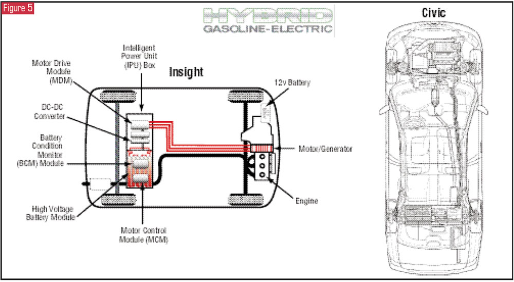
Figure 6 shows the actual battery module with MDM/DC-DC converter cooling fan along with the BCM and MCM mounted on top of the assembly. Figure 7 is the battery-module assembly turned around so that you can see the Ni-MH batteries, manufactured by Panasonic EV Energy, which produce terminal power of 144 volts.
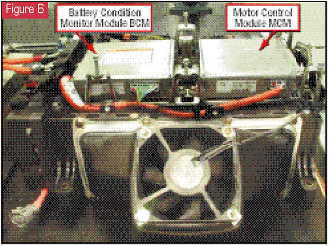
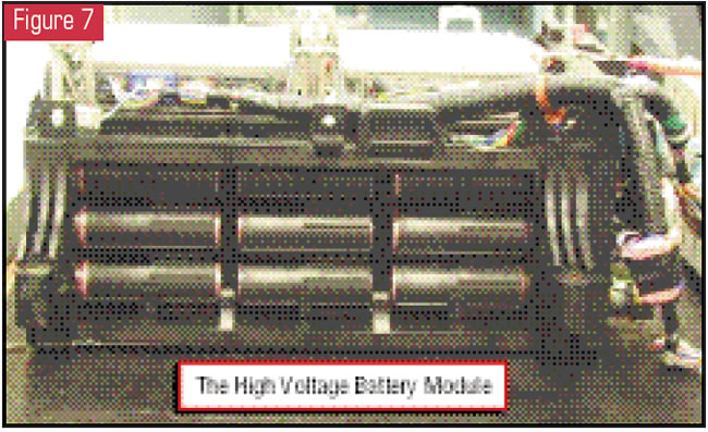
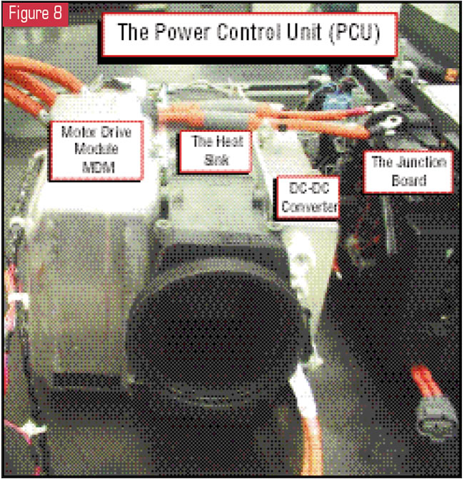
Figure 8 shows the MDM, which is placed alongside of and connected to the battery module through a junction board. The MDM, the heat sink and the DC-DC converter are collectively the power control unit (PCU). Mounted alongside the DC-DC converter internally and out of sight is a motor-power inverter (MPI) module.
By now you may be wondering, “What does all this stuff do and why is this in a magazine that is supposed to be about automatic transmissions?” Welcome to the world of drivability and electronics, where the electronics have much to do with how the transmission will function. And the Honda hybrids make the phrase that Emeril the chef made famous – “Bam!
Let’s kick it up a notch!” – look like child’s play. And, of course, the adage is, “You have to know how it works before you can fix it.”
In reality, this system is less complicated than the one on the Toyota Prius. Take a look at Figure 9. What you will see is that the motor control module is the big bad computer of the bunch. It monitors, controls and influences the entire powertrain system. The BCM module tells the motor control module when the high-voltage batteries need charging. The motor control module then signals the motor-power inverter to charge the batteries. When the batteries do not need charging, the motor control module controls the IMA motor through the motor-power inverter.
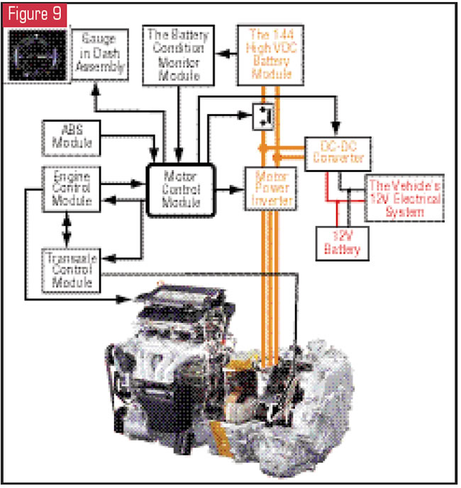
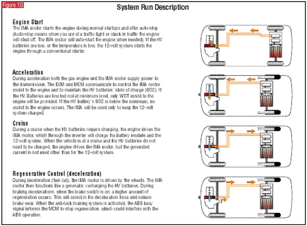
With that said, the motor-power inverter converts the 144-volt DC from the battery module to alternating current, which operates the IMA motor to supply power into the transmission. When the IMA motor is acting as a generator, the motor-power inverter converts the AC voltage back to high-voltage DC. The DC-DC converter steps down the high-voltage DC to the standard 12 volts needed for the rest of the vehicle. And as the father in the movie “My Big Fat Greek Wedding” would say, ”and there ya go” – a simple little overview of all these modules and batteries. Figure 10 then goes on to provide operating modes of the IMA system.
Most of these modules are in what is called an intelligent power unit (IPU) box. The IPU is in the rear hatchback area of the Insight, whereas in the Civic it is behind the rear seat. You need to know this if you are going to work on the transmission, as you must “power down” the system before working on these vehicles. And with the IMA motor being between the engine and transmission, those high-voltage wires in bright-orange conduit are right there in your working area.
With the Insight, when you open the rear hatch you must lift the carpet to gain access to the switch that powers down the system. Once the carpet is lifted, you will need to remove a screw-down cover to gain access to the switch. You also will find a very clear message written on a tag near the switch cover (see Figure 11). Of course, being the technicians that we are, we flipped the switch to the off position with a 6-foot wooden broom handle just so we could show you what it looks like with the cover removed (see Figure 12) – the sacrifices one makes for the transmission industry!
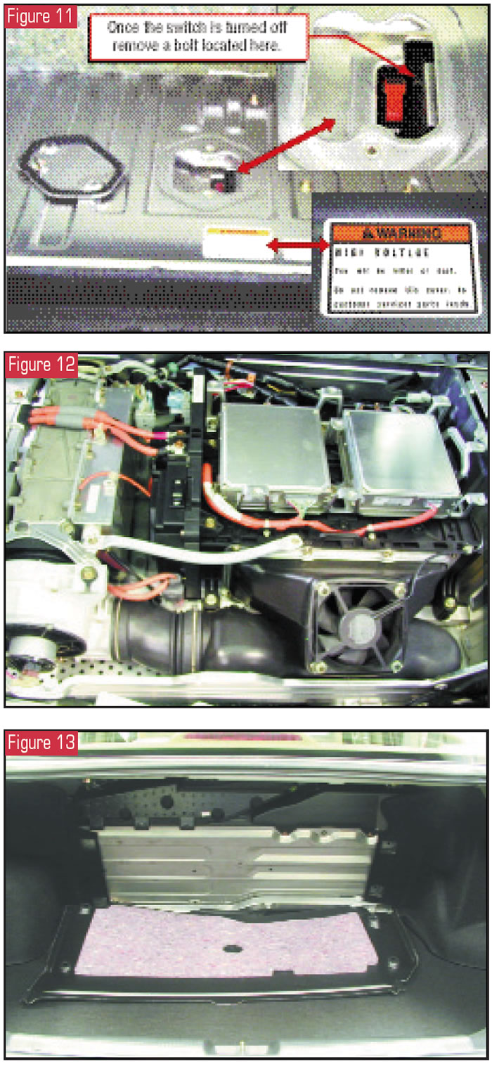
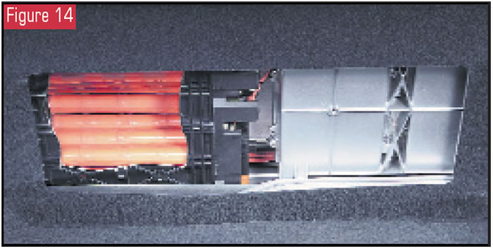
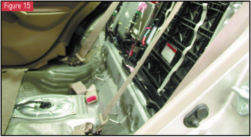
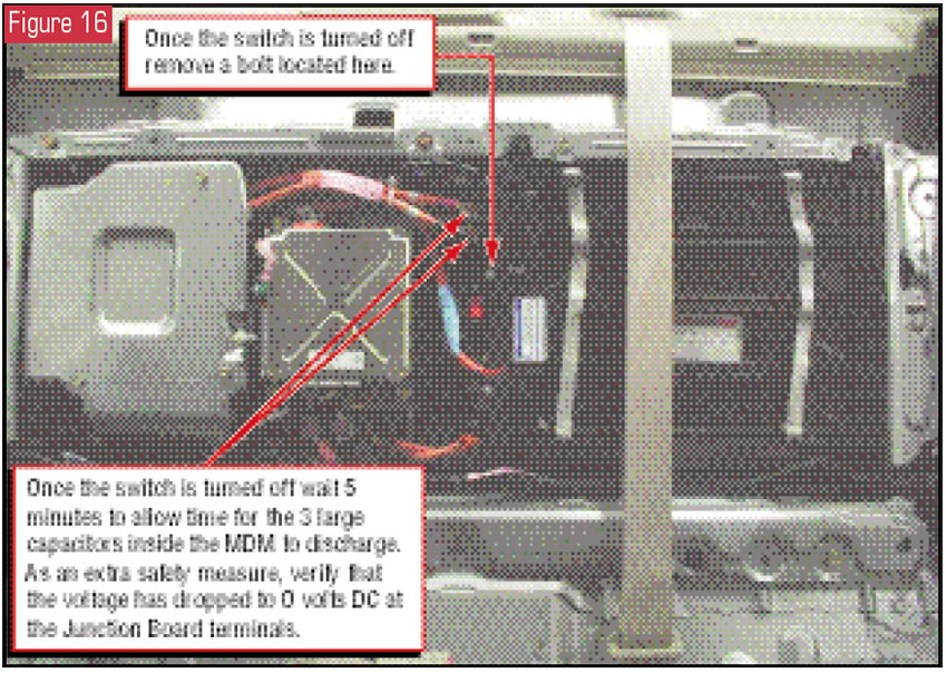
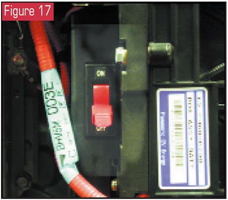
The Civic hybrid is a little different from the Insight. If you open the trunk and remove the carpet, you will find a metal panel (see Figure 13). Figure 14 provides a cutaway view to give you an idea of how the IPU box is set in place. Of course, we do not recommend the use of an air chisel here. What you will need to do is remove the back seat (see Figure 15). Once the seat is removed (see Figure 16), the entire IPU box is visible, and dead center – I mean right in the middle – is the on/off switch used to power down the system before you commence any work (see Figure 17). It is important to wait for five minutes after turning off the switch to allow the three large capacitors in the MDM to discharge. You can check with a DVOM at the terminals on the junction box to verify that there is no voltage in the system. Disconnect the two wires and wrap the ends with electrical tape for added safety. Also, if you have been medically treated with a pacemaker, do not hold the IMA motor close to your body.
Now that the switch is shut off, work on the transmission can begin. And that is where we will pick it up next month. Of course, by that time the capacitors should be fully discharged.
Special thanks to the boys at South Motors Honda for their hospitality, and to Honda American Motor Co. Inc. and for the cooperative efforts of Danilo Aranaga, the export training coordinator for Honda.


