
Technically Speaking
- Author: Wayne Colonna, Technical Editor
The idea of a stepless-ratio transmission, otherwise known as a continuously variable transmission (CVT), is not new technology. If I have my history right, among Leonardo da Vinci’s many sketches of inventions was a drawing that implied the possibility of a stepless continuously variable transmission.
In 1886, German automotive engineers Gottlieb Daimler and Karl Benz built the first CVT using a rubber V-belt that rode between two shallow cones. For those of you who are not familiar with snowmobiles or all-terrain vehicles (ATVs), CVTs are the commonly used transmission in these vehicles. The first passenger car with a CVT that found itself in the United States was back in 1959, when DAF (Doornes Automobiel Fabreiken) introduced a twin-cylinder 600cc car called the Daffodil with a “Variomatic” belt drive.
Then from 1990 to 1994 we had the short-lived Subaru Justy, followed by the 1996-99 Honda Civic HX. To date, literally hundreds of designs for CVTs have been submitted for U.S. patents. If you visit http://www.gizmology.net/cvt.htm, you will have an opportunity to see some basic CVT designs as well as a link to the United States Patent Database.
What makes the CVT desirable is that its design optimizes the torque produced by the engine. Not only is the efficiency of power transfer superior to that of a conventional automatic transmission using a torque converter, but acceleration and cruise conditions also are improved because of the available varying ratios. And Honda is no slouch when it comes to CVTs, as it has been designing and building them as far back as the 1980s to be used in its ATVs. So it makes sense that Honda would design a hybrid vehicle using a CVT.
Figure 1 shows a CVT used in Honda’s Civic HX in the 1996-99 model years. This is a typical gasoline-powered passenger car, and the model designation for this CVT is the M4VA. The CVT used in the Honda Insight has the model designation MHTA. Although these two CVTs are similar in operation, there are definite differences between them. When Honda introduced the Civic Hybrid in 2003, modest changes occurred to the CVT, which received the model designation SZCA (see figures 2 and 3).
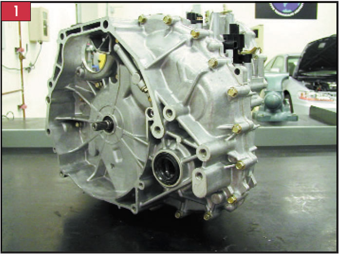
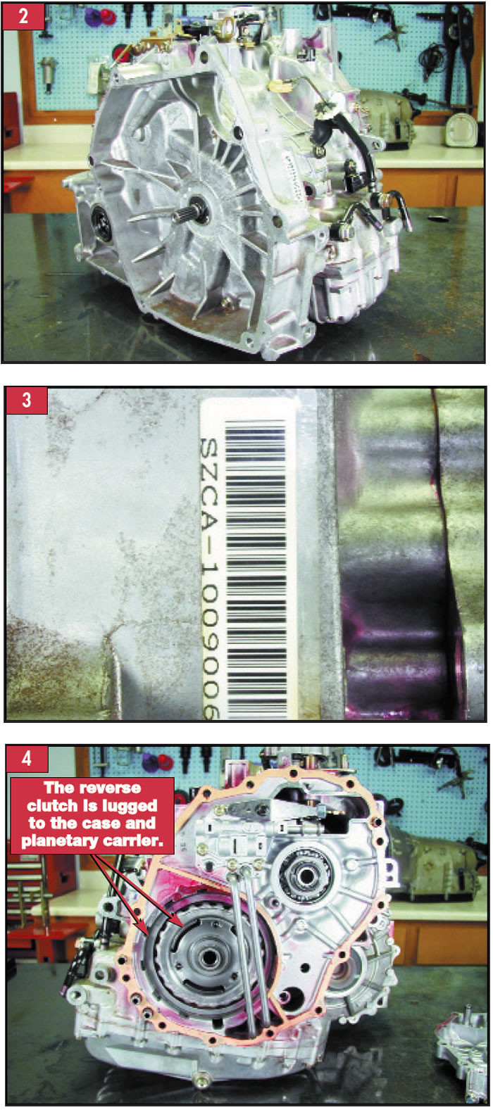
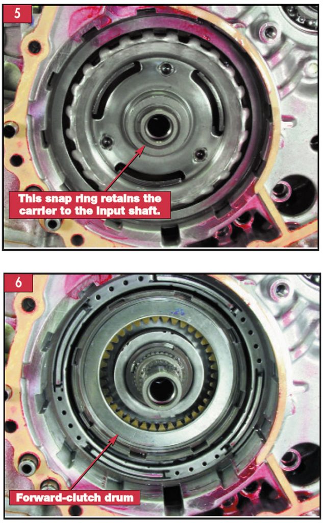
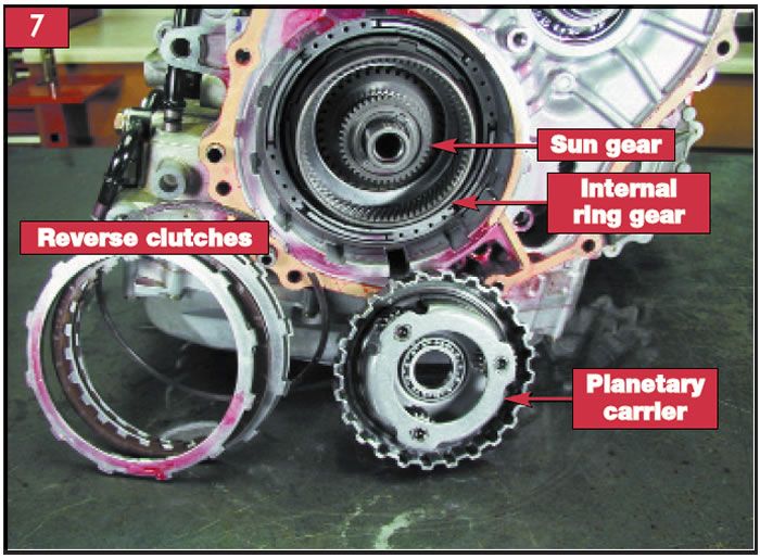
Figure 4 shows the Civic Hybrid’s CVT with the end cover removed, making the manual valve body, feed pipes, the reverse clutch and the back side of the input shaft and planetary-carrier assembly visible. When these parts are removed (the planetary-carrier assembly slides off the input shaft after removal of the rear retaining snap ring shown in Figure 5), the forward clutch becomes visible and accessible (see Figure 6). It is through these components that torque from the engine is supplied to the drive-pulley shaft in either a forward or reverse rotation. Since the planetary assembly is not used to provide different gear ratios, providing reverse and forward rotation is its only job requirement. And it accomplishes this task through the sun gear as the input member and the forward-clutch housing as the output member to the drive-pulley shaft (see figures 7, 8 and 9).
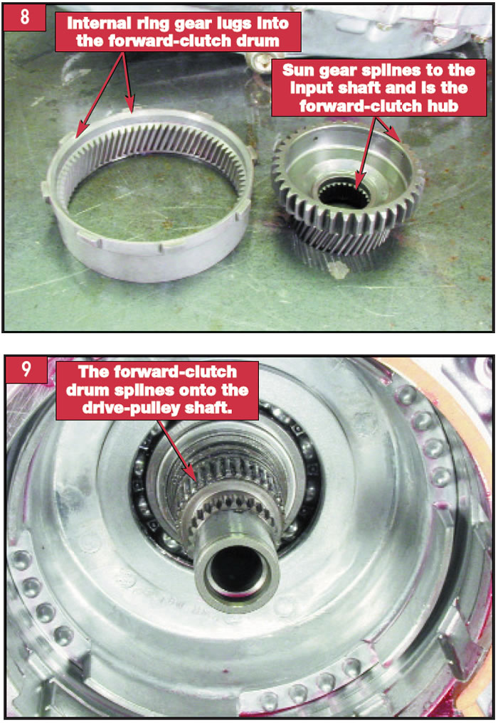
The arrangement goes like this:
The input shaft splines into the sun gear, which also serves as the forward-clutch hub. The internal ring gear lugs into the forward-clutch drum, which splines into the drive-pulley shaft. The reverse-clutch assembly in the intermediate housing lugs to the pinion carrier, which when applied holds the carrier stationary.
Although you may need to read that paragraph a couple of times, what actually occurs is quite simple. Whether forward or reverse, the sun gear rotates anytime the engine is driving the input shaft. If the selector lever is placed into reverse, the reverse clutch is applied, holding the carrier stationary, and the sun gear forces the little pinion gears in the stationary carrier to rotate in the opposite direction. This also forces the internal ring gear to rotate in the opposite direction. The internal ring gear is mechanically connected to the forward-clutch drum, which is splined to the drive-pulley shaft. The drive pulley then is driven in the same reverse rotation.
When the selector lever is placed into any of the forward ranges, the engine is driving the sun gear through the input shaft. The forward clutch is applied, locking the drum to the rotating sun gear. The forward drum is mechanically linked to the internal ring gear. This means that two members in the planetary gearset are spinning in the same direction at the same speed. That locks the entire gearset to spin as one member. And with the forward-clutch drum being splined to the drive-pulley shaft, power is delivered to the drive-pulley shaft in a forward rotation.
As a side note, the planetary gearset used in the earlier Honda Civic HX’s CVT is arranged slightly differently from those in the Insight and Civic Hybrid. The difference is that the reverse clutches hold the internal ring gear and the carrier is mechanically connected to the forward-clutch drum (see figures 10 and 11). The end result of a forward or reverse rotation remains the same.
Getting back to the Civic CVT on the bench, with the flywheel housing removed, the differential assembly, the start-clutch assembly and the pump assembly are visible (see Figure 12). A chain drives the pump through a sprocket that is splined to the inboard part of the input shaft slightly behind the tip of the shaft where the damper drive-plate splines are. Notice that the start-clutch assembly is just above and to the left of the input shaft. This assembly is pressed onto the tail end of the driven-pulley shaft. As you look slightly to the lower left of the start clutch, you will find the secondary driven gear on the final-drive shaft. The start clutch uses this gear to transfer power from the pulley and belt assembly to the differential assembly (see Figure 13).
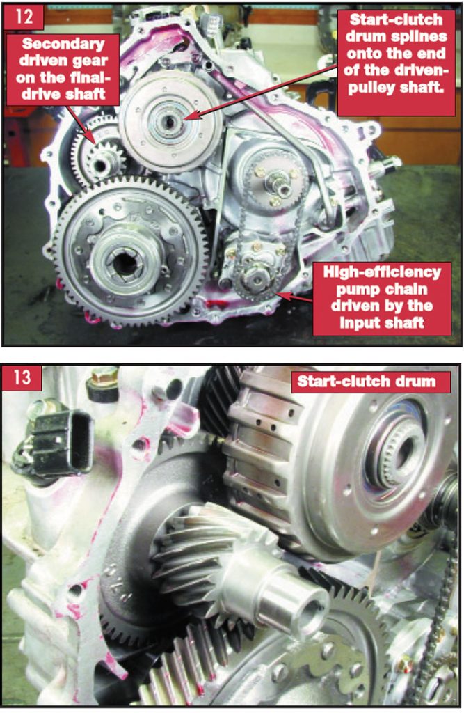
This multi-purpose start clutch will allow the engine to idle during a stop with the transmission in gear. A computer strategy provides a creep function through the clutch for easy low-speed driving and on-hill take-offs with capability to hold the car stationary on a 4% grade. It has a controlled slip on take-off for pleasability and drivability and goes to full apply at normal to maximum throttle, providing an efficient transfer of power and fuel economy.
When the clutch is completely disengaged, it isolates the pulleys and belts from the front wheels. This prevents extreme internal damage should the vehicle be towed with the front wheels on the ground. During hard-braking, rapid-stop situations, this strategic location allows for the start clutch to release while the belt and pulleys remain in rotation, changing ratios in preparation for an on-throttle take-off.
For all practical purposes, this start clutch replaces the torque converter, and since it is designed to slip at various times, a high volume of lubrication fluid (about 8 liters a minute) is forced through the frictions to help dissipate heat. This type of fluid flow explains why the drum has so many exhaust holes.
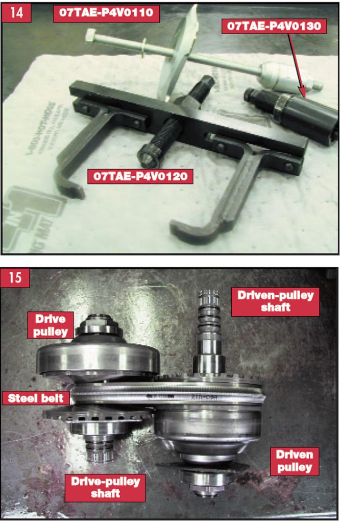
Figure 14 shows some “essential tools” from Honda that will remove and install this start-clutch drum with ease. And once the start-clutch drum is removed, the unit can be stripped down to the heart of the transmission – the belt and pulleys (see Figure 15).
Operation and control of the pulleys by the valve body and solenoids, hydraulics, and common problems with the CVT from the Civic HX to the Civic Hybrid will be the final installment of this series on hybrid vehicles and the world of CVTs.
Thanks to Frank C. Kuperman of Phoenix Remanufactured Transmissions for supplying a CVT transaxle from a Civic Hybrid vehicle to photograph for this and next month’s articles.


