Up To Standards
- Subject: Operating principles of transfer cases
- Essential Reading: Rebuilder, Shop Owner, Center Manager, Diagnostician
- Author: Mike Weinberg, Rockland Standard Gear Contributing Editor
The transfer case is a very simple concept. It is basically a power divider mounted on a transmission that is capable of splitting torque produced by the engine to drive both sets of axles on the vehicle.
For years these basic systems required the driver to select which mode the vehicle was in, using one or more shift levers, and the vehicle needed to be stopped so the driver could lock the front-axle hubs and transfer power to the front wheels. The next development was automatic locking hubs, which no longer needed driver involvement to function.
About this time the manufacturers began to develop full-time four-wheel-drive systems that would engage four-wheel drive, without requiring any action on the driver’s part, whenever a driving wheel would begin to slip. These early systems used an internal differential in the transfer case to split torque between the front and rear axles and were very inefficient with regard to fuel economy. If you remember the NP 203 transfer case, you also remember many owners converting their automatic locking hubs to manual hubs to save gas.
At this point four-wheel drive became the rage and the sport/utility-vehicle trend began. The idea of safe, all-weather operation, coupled with the space our citizens needed to haul around all the aspects of their lifestyles, was a commercial hit. People who never had any intention of going “off road” in a vehicle were now involved in four-wheel-drive vehicles. The designers created transfer cases that needed no input from the driver and had active or “automatic” capability to engage the front axles in the event of rear-wheel slippage without the driver ever knowing it was happening.
This article describes the different operating systems involved to create an understanding of the principles that you will need to be able to diagnose problems. The terminology here is very important, and without a clear understanding of what each term means we have confusion and wasted effort.
Four-wheel-drive systems are broken down into two main categories: four-wheel drive (4WD) and all-wheel drive (AWD), the difference being that 4WD systems offer some measure of driver control and AWD systems are always available with no driver input; in other words, they cannot be turned off.
To further divide the classes of 4WD transfer cases, we have active or automatic transfer cases and manually shifted units. The active or automatic transfer case has a position in which the vehicle will operate in 2WD until the rear-wheel speed exceeds the front-wheel speed, at which time the transfer case will send more torque to the front wheels until the shaft speeds equalize. All this takes place without the driver’s involvement if the unit is operating in the active or automatic mode.
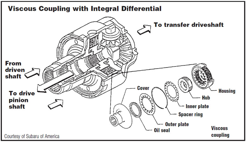
AWD units and active or automatic 4WD units achieve this torque split through several different designs. The first is a viscous coupling, which is a sealed drum containing alternately splined steel discs that are spaced so that they never make contact with each other. Also present in the coupling is a small quantity of a silicone-based fluid that is very temperature sensitive and expands rapidly to fill the container. When one of the shafts to which the discs are splined begins to turn faster than the other one, the fluid expands because of the heat generated and the alternate discs are locked together by the high “shear” effort of trying to turn through the fluid. Once the discs are locked up through this shear force (not plate-to-plate contact), power is transmitted to the front propeller shaft and sent to the front wheels. When the shaft speeds are equalized and the silicone fluid inside the coupler cools, it contracts (changes viscosity) and the shear effort between the plates subsides so that power is transmitted to only the rear drive wheels.
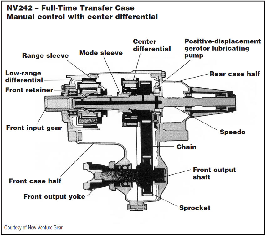
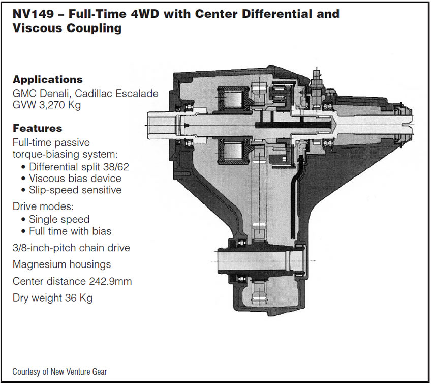
The second option is a differential within the transfer case. These usually resemble a planetary gear and are sometimes called a planetary type of differential. When the rear-wheel speed exceeds that of the front wheels, the differential will send power to the front driveshaft via the drive chain to equalize torque between the front and rear prop shafts. This happens because of the design of the planetary-differential components. One part of the differential is splined to the main shaft, and there is an intermediate clutch shaft and an internal gear to the differential that is splined to the drive sprocket to operate the chain connecting it to the front output shaft.
Some transfer cases have both a viscous coupling and a transfer-case differential.
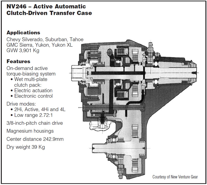
The third method of achieving active or automatic 4WD is through the activation of an internal clutch pack in the transfer case. This is a more-complicated design because clutch application is provided by computer control. The computer will measure and compare front and rear prop-shaft speeds, wheel speeds, throttle angle, transmission range and other factors to activate the clutch pack. The same general operation happens when the computer senses a difference between wheel speeds and prop-shaft speeds and applies the clutch pack to send torque to the front wheels. Again, when shaft speeds equalize, the clutch pack will be disengaged and the vehicle will return to 2WD.
Many of the automatic or active transfer cases contain clutch-pack systems, and the diagnostic routines are very complex because of all the components and systems involved. Remember that all these designs are an integration of multiple systems on the vehicle. You have engine-management computers, chassis computers and body computers involved, because these systems must function together. So we now have a transfer case that is being controlled in relation to engine operating parameters, ABS operation, stability-control programs and traction-control systems.
The clutch-pack type of active or automatic transfer case suffers from certain internal issues that need to be dealt with during diagnosis and repair. The clutch-pack application is handling a very high torque load. The application of the clutch puts a tremendous load on the internal bearings in the transfer-case assembly, and bearing wear and case wear are very common. Be aware that these units frequently will require case replacement and new bearings and shims, besides replacement of worn or damaged clutches in the pack. Certain designs require major machine work internally to correct internal case geometry to get the side loading off the shift rails. The BW 4405 is a prime example of this; just replacing the worn internal components is not enough to create a successful repair.
All the active-transfer-case designs are very sensitive to certain conditions. Fluid is extremely important to the correct operation of clutch-pack-driven transfer cases. An incorrect fluid or fluid that is contaminated or in which the additive package is worn out will result in failure of the clutch-pack operation.
Tire sizes and pressures are also critical to operational life and quality. This is an area that needs to be carefully explained to your customer and included in your warranty, because you will not be able to check on these conditions after the vehicle leaves your shop. If the tires have different rolling ratios because of different sizes, or if they have 3 or 4 psi of air-pressure difference between them, they will cause the internal components to respond as if there were a slipping condition and activate the transfer of power to the front wheels. This is particularly dangerous with viscous-coupling designs.
The tire size does not have to be visibly different. The sidewall label is not accurate for this purpose, and you have to measure the tire circumference with a stagger gauge or a tape measure around the tread. All tires must be within 1/4″ in circumference. If they are not, the viscous coupling will interpret the difference in speed as a slip and begin to send power to the front wheels. Because the tire size will never be corrected, the viscous coupling will never shut off and will burn itself up in a very short time at highway speeds. Tire-size mismatch also will cause all kinds of codes to be set with computer-controlled clutch-pack-driven units.
Another issue is towing. It is not safe to tow any of these vehicles for any extended period. Certain owner’s manuals may say something different, but they are just making more work for you. On a differential type of unit, towing a vehicle with the front wheels on a dolly destroys a differential in short order. States that have dynamic vehicle inspections on chassis dynos create the same kind of damage immediately, and many vehicles now are not required to pass those tests. There is no safe way to tow these vehicles for any real distance with the prop shafts connected.
It has been my experience in a lifetime of auto and transmission repair that few if any vehicle owners actually read the operating manual. It is up to you to explain to your customer the proper operation and use of their vehicle, or else you will wind up having heartfelt discussions about warranty issues that you really won’t win.
For instance, there is no transfer case that can be operated on dry pavement in 4WD. As the vehicle moves through turns and lane changes, the wheels turn at different speeds. Obviously, the inside wheels in a turn move through a shorter arc than the outside wheels. If the vehicle is locked in 4WD, that means that you get a 50/50 torque split front to rear and the internal components will spline-lock because of the different wheel travel. Now there will be a jump or bang when the forces load up so much pressure on the components that the wheel has to spin to release the torque load.
All these units are designed to operate on wet pavement, snow, sand, grass or dirt when locked in 4WD, because these surfaces permit wheel spin during turns so internal spline lock does not occur. The design of active or automatic transfer cases was created so the vehicle can be driven in the automatic mode on dry pavement with 4WD being engaged only when needed, and the unit does not remain locked up on dry pavement.