TC Tech Tips
- Subject: Converter rebuilding techniques
- Unit: 6R60
- Vehicle Application: Ford Explorer, F-150
- Essential Reading: Converter Rebuilder, Transmission Rebuilder, Diagnostician
- Author: Ed Lee
It’s like Skinning a Cat (There’s more than one way)
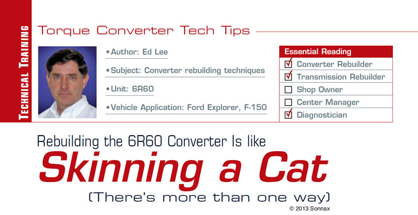
Ford introduced the 6R60 transmission in 2005, when it was originally used for Explorers equipped with the 4.6L gas engine. In 2008 and 2009, the 6R60 transmission also was used in some 4.6L F-150 pickups. The 6R60 transmission comes with a multi-plate, captive-clutch converter with a unique design. One single-sided clutch disc rests against the cover. This clutch disc has 12 tangs that engage the turbine arranged in groups of three around the disc’s outer diameter. The clutch disc is sandwiched between the cover and a two-sided clutch disc that is attached to the cover in six positions close to its inner diameter(Figure 1).
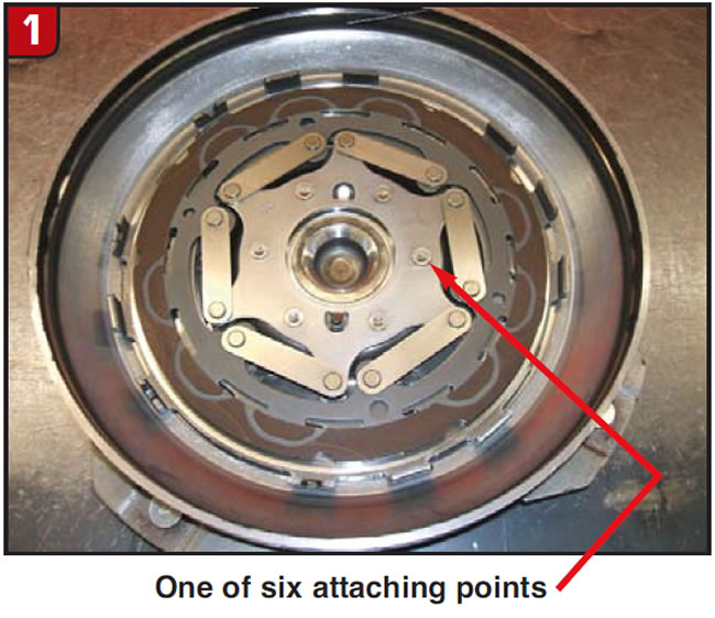
The outside of the cover has six cavities that correspond to the positions of the attaching points of the two-sided clutch(Figure 2).
The mushroomed ends of the attaching members appear to be rivets, and the cavities in the cover appear to be the rivet heads. In reality they are not rivets but are actually stands that result from a transfer of metal caused by a pressing action. The cavities in the cover are the absence of the metal that was transferred into the stands.
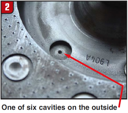
The first generation of the 6R60 converter used a complex, two-sided clutch design.
The center section was attached to the clutch by six spring-steel straps retained at each end by a rivet(Figure 3).
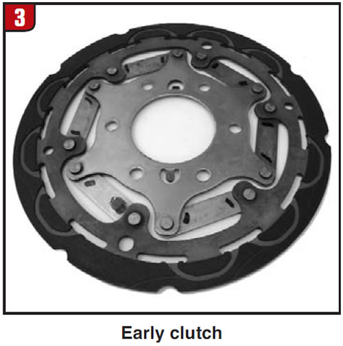
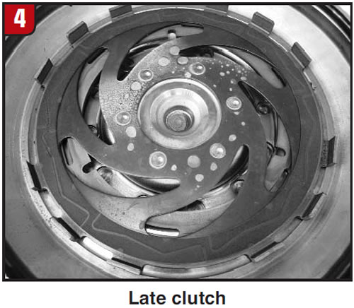
The second generation used a one-piece, two-sided clutch(Figure 4).
The cover, single-sided clutch and method of attaching the two-sided clutch to the cover remained the same for both generations. All 6R60 OE-remanufactured converters are second-generation, even if they started life as first-generation converters.
Many different methods have been used to successfully rebuild the 6R60 converter.
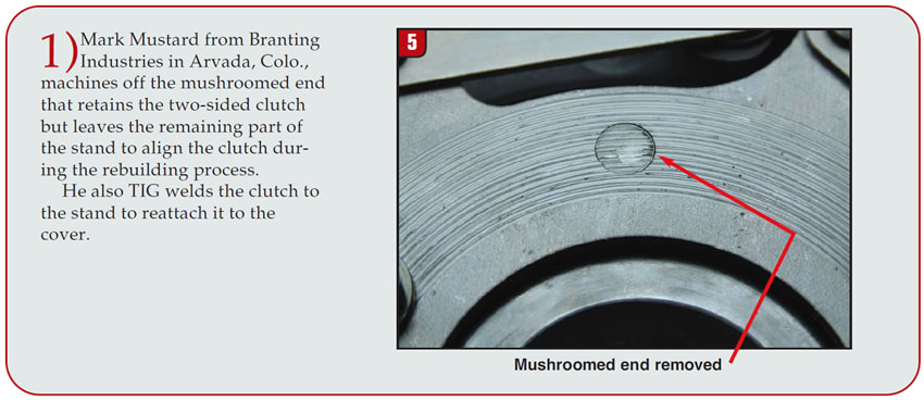
- 1) Mark Mustard from Branting Industries in Arvada, Colo., machines off the mushroomed end that retains the two-sided clutch but leaves the remaining part of the stand to align the clutch during the rebuilding process. He also TIG welds the clutch to the stand to reattach it to the cover.
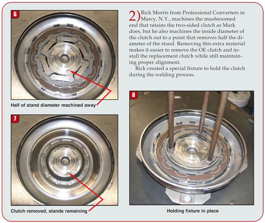
- 2) Rick Morris from Professional Converters in Marcy, N.Y., machines the mushroomed end that retains the two-sided clutch as Mark does, but he also machines the inside diameter of the clutch out to a point that removes half the diameter of the stand. Removing this extra material makes it easier to remove the OE clutch and install the replacement clutch while still maintaining proper alignment.
- Rick created a special fixture to hold the clutch during the welding process.
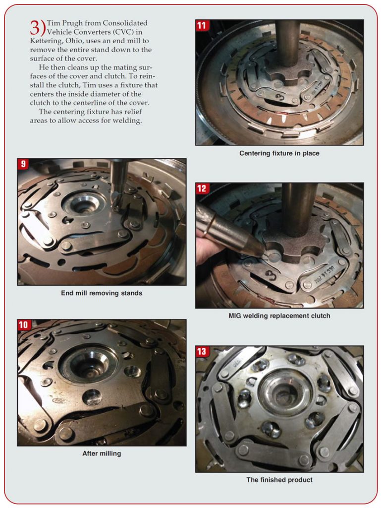
- 3) Tim Prugh from Consolidated Vehicle Converters (CVC) in Kettering, Ohio, uses an end mill to remove the entire stand down to the surface of the cover. He then cleans up the mating surfaces of the cover and clutch. To reinstall the clutch, Tim uses a fixture that centers the inside diameter of the clutch to the centerline of the cover. The centering fixture has relief areas to allow access for welding.
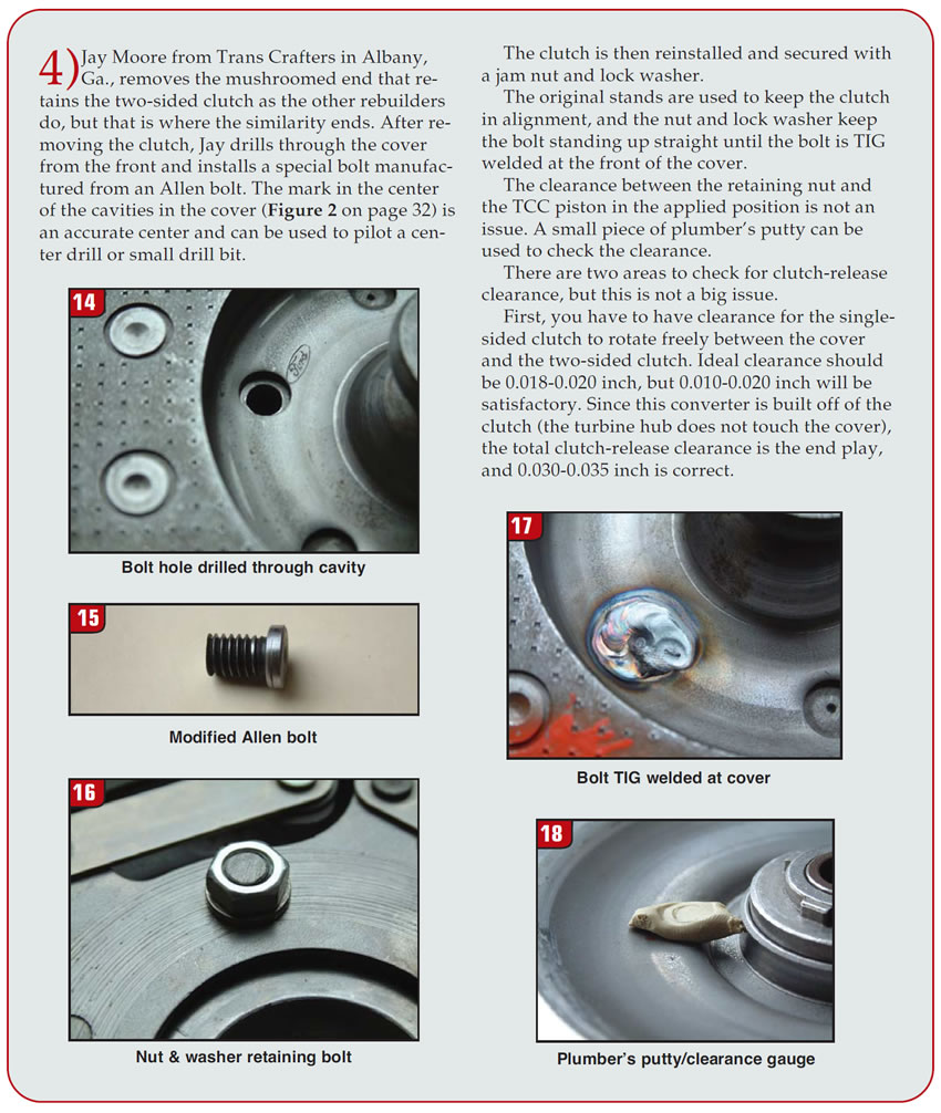
- 4) Jay Moore from Trans Crafters in Albany, Ga., removes the mushroomed end that retains the two-sided clutch as the other rebuilders do, but that is where the similarity ends. After removing the clutch, Jay drills through the cover from the front and installs a special bolt manufactured from an Allen bolt. The mark in the center of the cavities in the cover (Figure 2) is an accurate center and can be used to pilot a center drill or small drill bit.
The clutch is then reinstalled and secured with a jam nut and lock washer.
The original stands are used to keep the clutch in alignment, and the nut and lock washer keep the bolt standing up straight until the bolt is TIG welded at the front of the cover.
The clearance between the retaining nut and the TCC piston in the applied position is not an issue. A small piece of plumber’s putty can be used to check the clearance.
There are two areas to check for clutch-release clearance, but this is not a big issue.
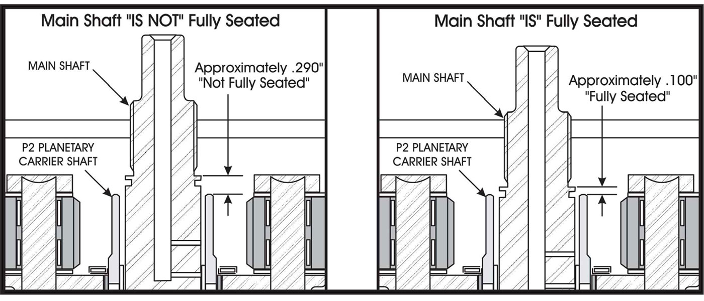
First, you have to have clearance for the single-sided clutch to rotate freely between the cover and the two-sided clutch. Ideal clearance should be 0.018-0.020 inch, but 0.010-0.020 inch will be satisfactory. Since this converter is built off of the clutch (the turbine hub does not touch the cover), the total clutch-release clearance is the end play, and 0.030-0.035 inch is correct.
Again, there is more than one way to skin a cat.

Special thanks to Mark Mustard, Rick Morris, Tim Prugh and Jay Moore for sharing their techniques and images.
Ed Lee is a Sonnax technical specialist who writes on issues of interest to torque-converter rebuilders. Sonnax supports the Torque Converter Rebuilders Association. Learn more about the group at www.tcraonline.com.
©2013 Sonnax