Torque Converter Tech Tips
- Subject: Repairing torque-converter stator
- Unit: 4L80-E
- Vehicle Application: GM trucks and SUVs
- Essential Reading: Converter Rebuilder, Transmission Rebuilder, Diagnostician
- Author: Ed Lee
When the 4L80-E was introduced in 1991 it became the flagship of the General Motors transmissions. With the exception of a few early dual-stator issues, this new transmission and converter had very few problems. In model year 2000, when the second-generation 4L80-E was introduced, the problems began.
The 4L80-E TCC pistons were cracking right from the start. The cracks developed just inside of the bond surface, much like what had been seen in the E4OD converters, and wreaked just as much havoc.
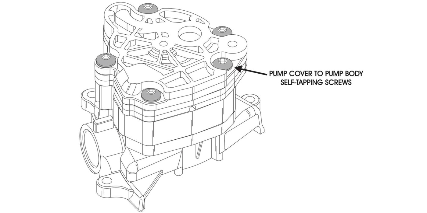
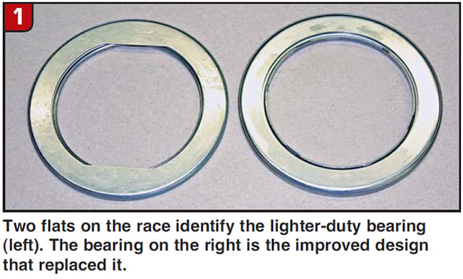
As if having another wave of cracking pistons was not bad enough, the problems with the second-generation stators were even worse. The first issue rebuilders noticed was excessive wear in the stator housing where the roller-clutch inner race contacts the housing. On some converters, the inner race would wear its way out through the stator housing and into the impeller hub. This was especially problematic because – unlike in the first generation – the impeller side of the stator was not a removable stator cap. The first-generation 4L80-E stators had thick stator caps at both the turbine and impeller sides and used very robust bearings. When the second-generation stator was introduced, the impeller-side stator cap was eliminated and a much lighter-duty bearing was used. This bearing can be identified by two flats on the inside diameter of the outer race (Figure 1).
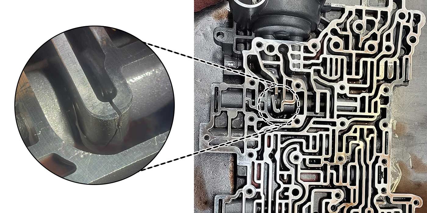
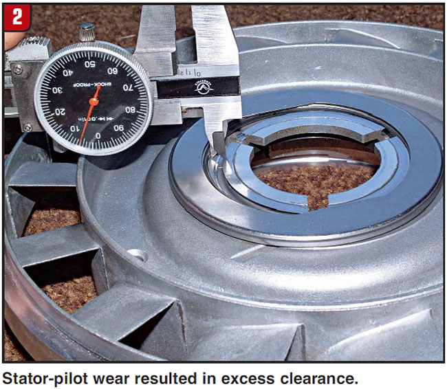
This bearing was notorious for having piloting issues as well as problems with its races cracking (Figure 2).
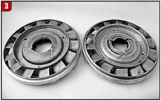
When the bearing race cracked and eventually broke off, it usually destroyed the stator and impeller (Figure 3).
GM eventually got this under control when the bearing was replaced with one that was 0.015 inch thicker through its cross section. The O.D. and I.D. dimensions of the bearing remained the same, but the flats on the I.D. of the outer race were removed.
The OE bearing with thinner races caused most of the damage to stators in second-generation units. Because of the severity of this damage, many considered these stators beyond repair, but that was not the case. When the roller-clutch inner race started wearing its way through the stator housing, the aftermarket responded with a repair plate. This repair option is very practical and, when properly approached, is well within the capabilities of most converter-repair shops.
Unfortunately, the stator bore for the roller-clutch outer race is the only machined surface accessible to lathe-chuck jaws on the turbine side of the stator. Because the stator has to be held from the turbine side to be machined for the repair process, the original approach was to remove the roller-clutch outer race to gain access to that machined portion of the stator bore for lathe-holding purposes.

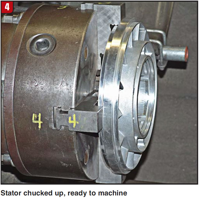
A far simpler technique is to machine the non-machined surface of the stator-body casting just forward of the blade mounting points. This can be done by holding the stator from the impeller side, where it is already machined for the stator outer-ring shoulder (Figure 4).
After machining of the new surface on the stator casting, the stator can then be held on the newly machined surface (Figure 5). When the stator is bottomed on the chuck jaws, it automatically runs true.
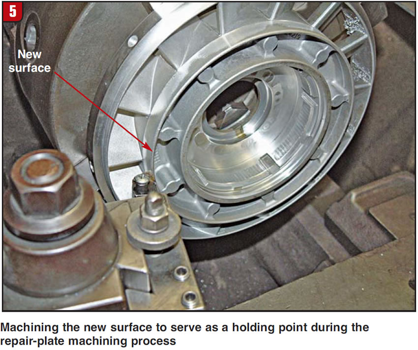
This method eliminates any alignment issues for machining purposes as well as the need to remove the roller-clutch outer race. The process is further simplified because the repair plate can be kept perpendicular to the bore by resting it against the roller-clutch outer race.
The only remaining critical issue is maintaining a snug fit between the repair plate and stator-housing bore. It is still important to have the roller-clutch outer race, roller-clutch inner race, stator cap and retaining ring in their proper locations during the process of welding the repair plate. This guarantees that the roller-clutch outer race is bottomed in the bore, that the repair plate will not distort during the weld process and – most important – that the retaining ring can still be installed after the repair.
New OE converters for this unit currently are running around $800. Considering the cost and availability of 4L80-E converter cores, this simpler approach to machining makes the repair plate a practical and extremely cost-effective fix.
Ed Lee is a Sonnax technical specialist who writes on issues of interest to torque-converter rebuilders. Sonnax supports the Torque Converter Rebuilders Association. Learn more about the group at www.tcraonline.com.
©Sonnax 2013