Body of Evidence
- Author: Jeff Parlee
- Subject Matter: Valve body
- Unit: A750E/F
- Vehicle Application: Toyota
- Issue: Avoiding assembly problems
There are some pitfalls that can trip you up with this valve body.
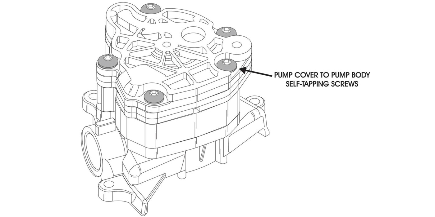
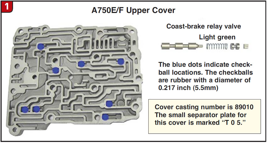
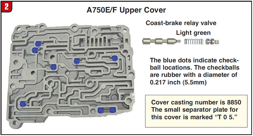
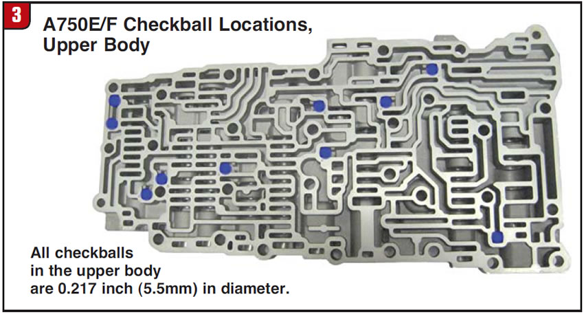
First, there are two different covers that can be found on top of the upper body. These covers have different casting numbers and different checkball configurations. The casting numbers are 89010 and 8850; I have seen only the 89010 checkball locations published. The checkball locations in the upper body are the same no matter which cover is on it (figures 1, 2 and 3).
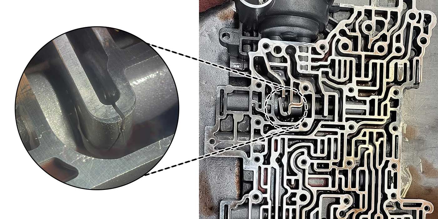
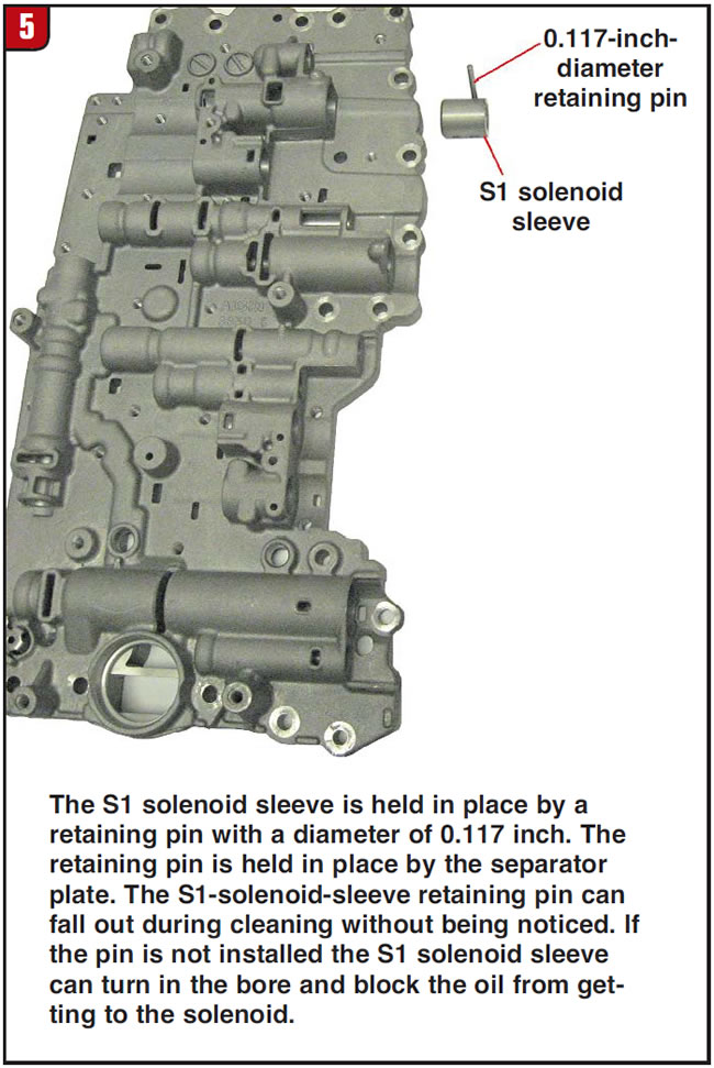
The second gotcha is the retaining pin for the S1-solenoid sleeve. The S1 solenoid is held in place by a bolt, but the solenoid slides into a sleeve. The sleeve is held in the correct position by a 0.117-inch-diameter pin. The pin is held in place by the separator plate. When the valve body is disassembled and cleaned, the pin may fall out of the lower casting and not be noticed. The sleeve usually stays in place, making it easy to overlook the missing pin. When the S1 solenoid is installed, a bolt holds it in place. The solenoid prevents the sleeve from coming out when the oil circuit is energized, but it does not keep the sleeve from turning and blocking off the oil circuit to the S1 solenoid (figures 4 and 5).
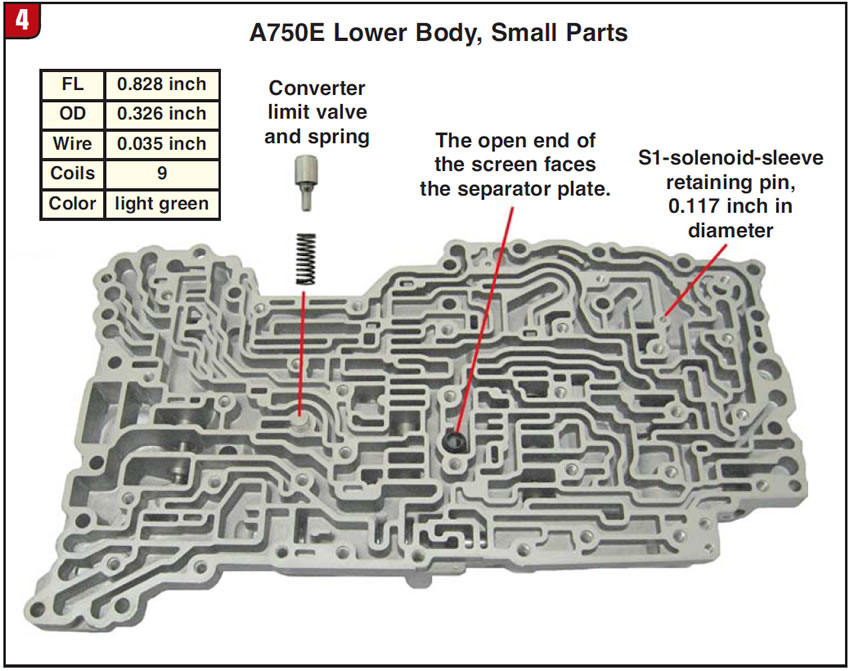

The lower body also has a barrel-type screen. Place the open end of the screen toward the separator plate. The converter limit valve and spring are also situated in the lower body. Install the spring first, then the valve with the stem into the spring (Figure 4).
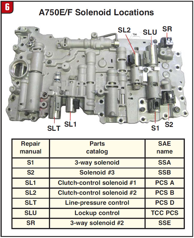
When assembling the valve body, install the manual valve into its bore before installing the SLU and SR solenoids (Figure 6).
Knowing the pitfalls before overhaul can make life a little easier.
Jeff Parlee is director of product support at ValveBody Xpress.