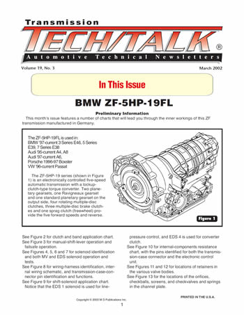
Issue Summary:
- This month’s issue features a number of charts that will lead you through the inner workings of this ZF transmission manufactured in Germany: BMW ZF-5HP-19FL.
The ZF-5HP-19FL is used in:
- BMW ’97-current 3 Series E46, 5 Series E39, 7 Series E38
- Audi ’95-current A4, A8
- Audi ’97-current A6,
- Porsche 1996-97 Boxster
- VW ’96-current Passat
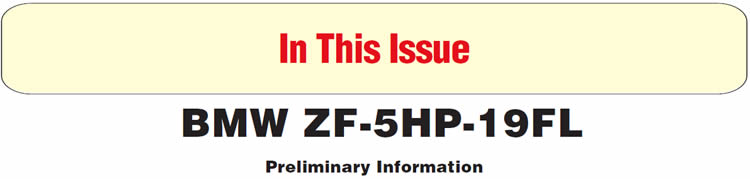
The ZF-5HP-19 series (shown in Figure 1) is an electronically controlled five-speed automatic transmission with a lockup-clutch-type torque converter. Two planetary gearsets, one Ravigneaux gearset and one standard planetary gearset on the output side, four rotating multiple-disc clutches, three multiple-disc brake clutches and one sprag clutch (freewheel) provide the five forward speeds and reverse.
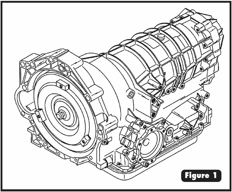
See Figure 2 for clutch and band application chart.
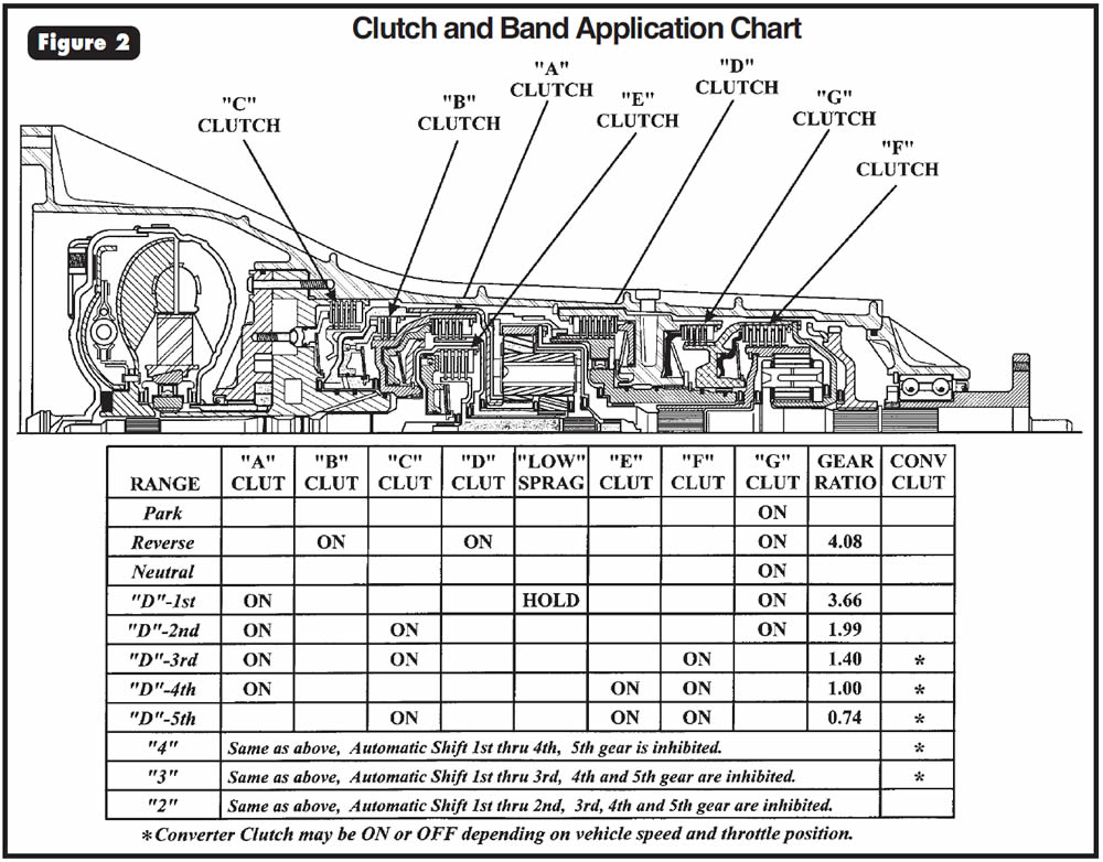
See Figure 3 for manual-shift-lever operation and failsafe operation.
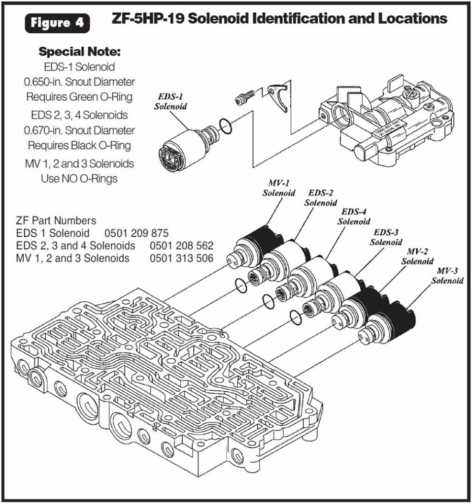
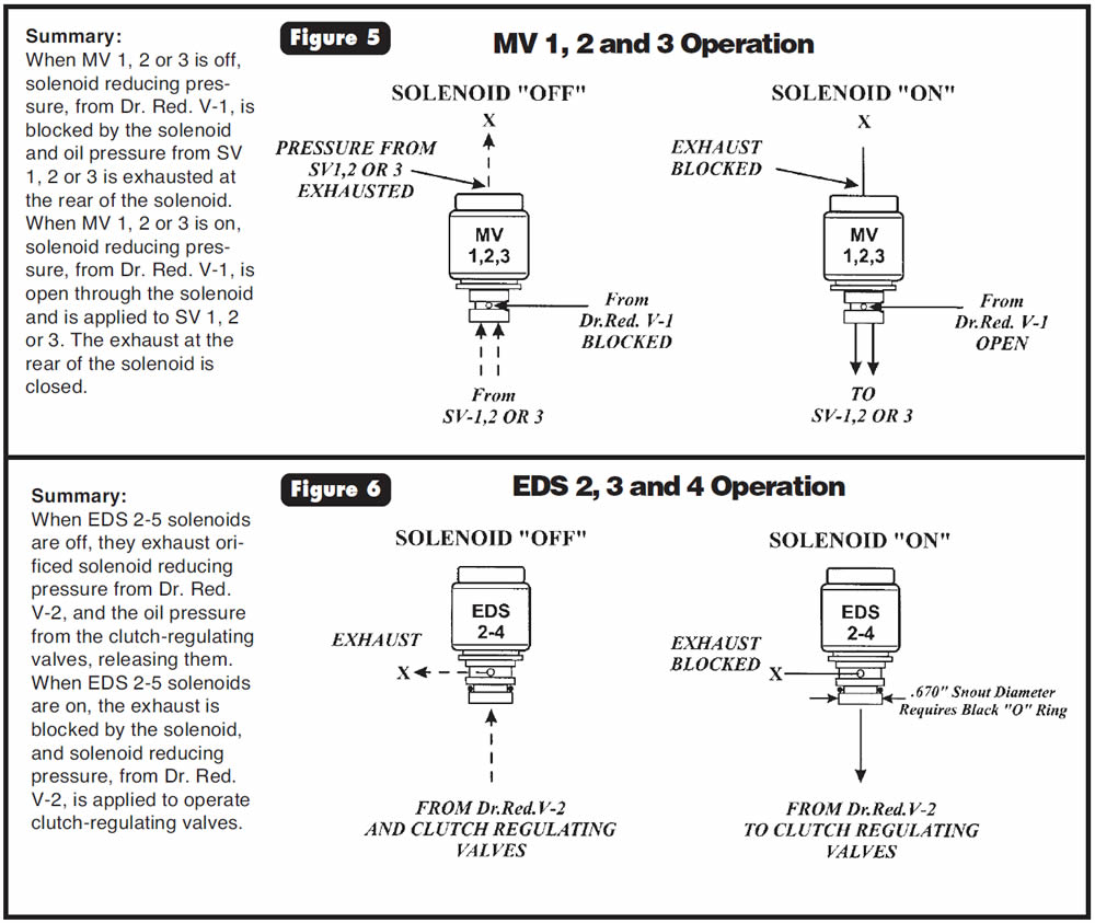
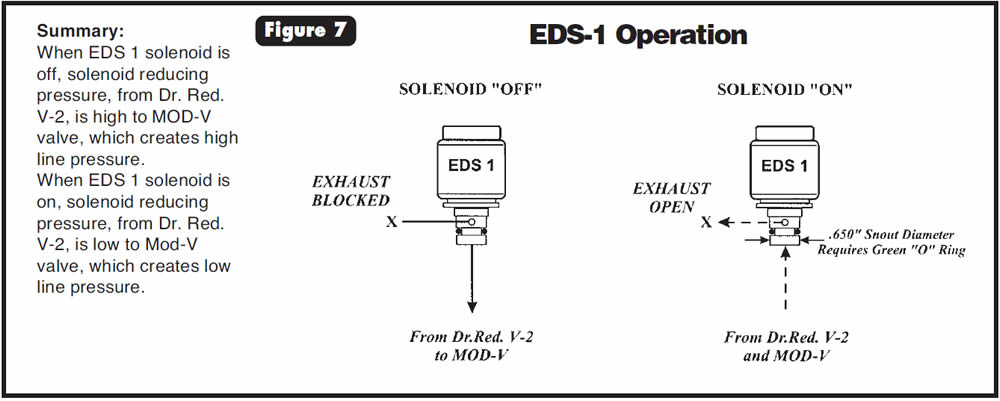
See Figures 4, 5, 6 and 7 for solenoid identification and both MV and EDS solenoid operation and tests.
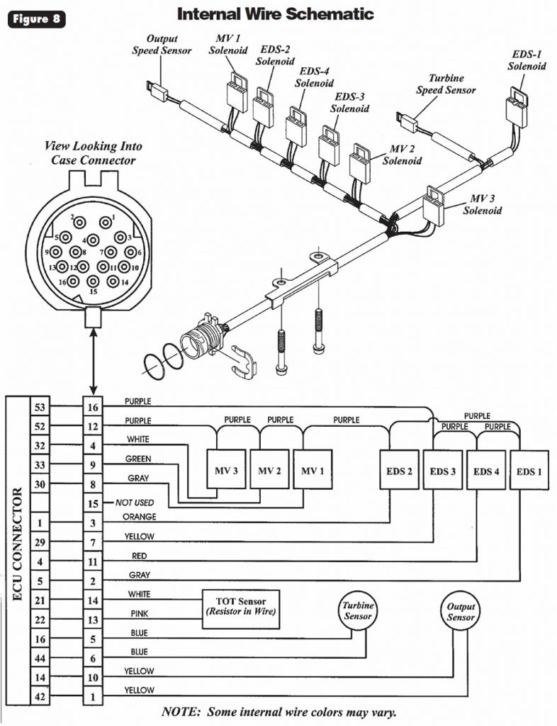
See Figure 8 for wiring-harness identification, internal wiring schematic, and transmission-case-connector pin identification and functions.
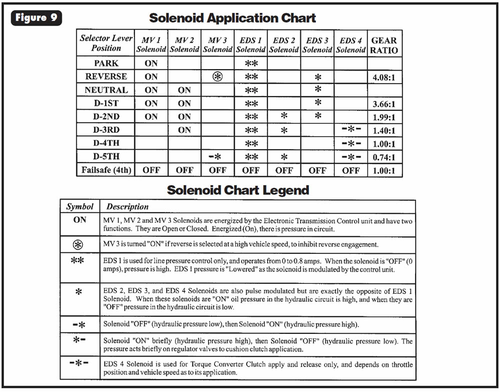
See Figure 9 for shift-solenoid application chart. Notice that the EDS 1 solenoid is used for line-pressure control, and EDS 4 is used for converter clutch.
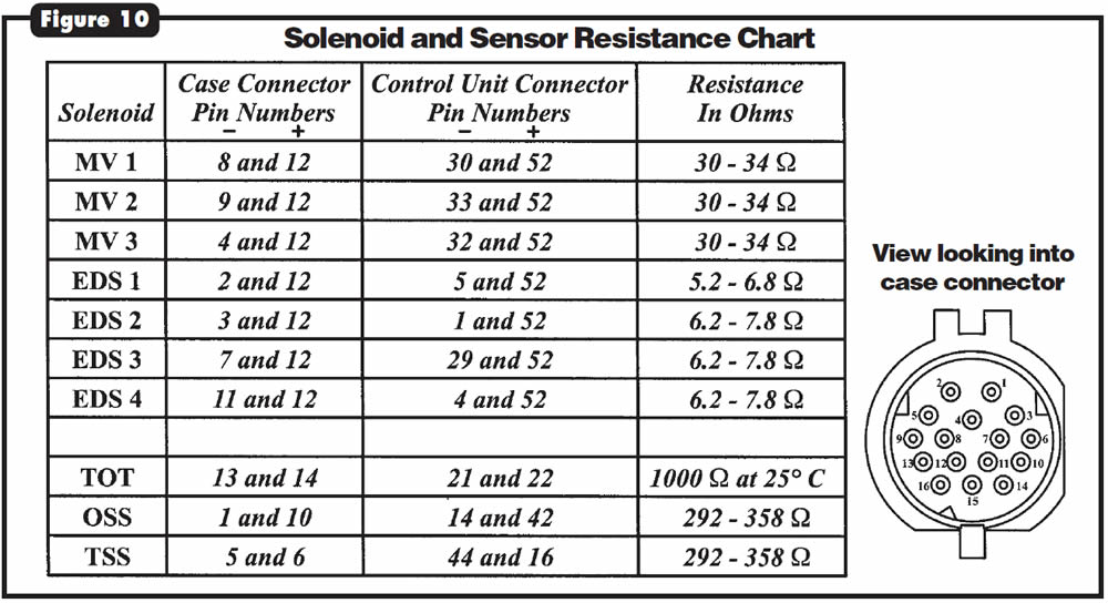
See Figure 10 for internal-components resistance chart, with the pins identified for both the transmission-case connector and the electronic control unit.
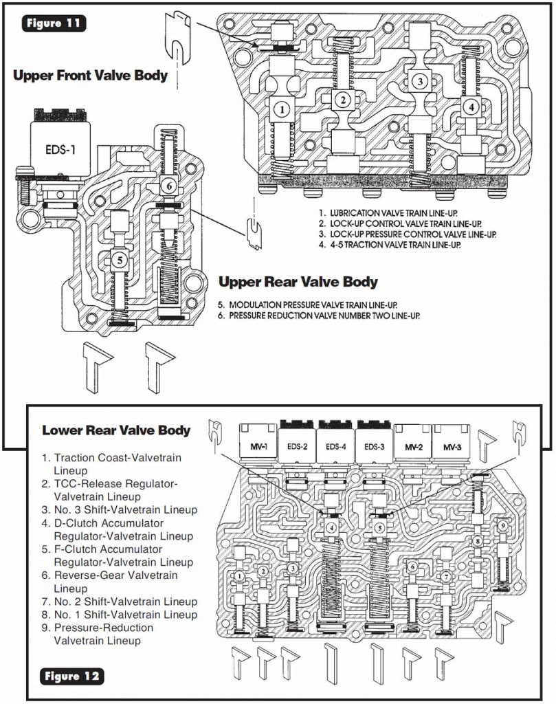
See Figures 11 and 12 for locations of retainers in the various valve bodies.
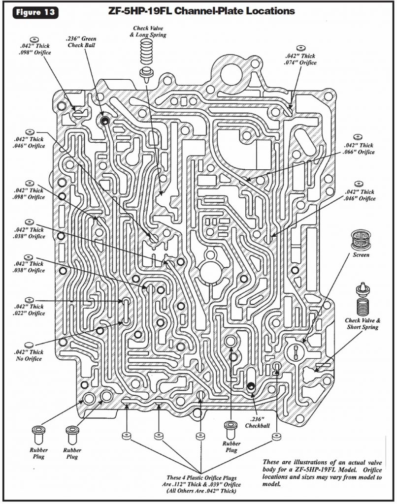
See Figure 13 for the locations of the orifices, checkballs, screens, and checkvalves and springs in the channel plate.


One-Touch-Control Versions
Standard versions have a shift quadrant using only the left gate (see Figure 3). The versions that are equipped with One-Touch Control, supplied as an option on certain models, have a two-section shift quadrant, also shown in Figure 3. Positions P, R, N, D, 4, 3 and 2 can be selected in the left-hand gate, and all shifts are automatic, depending on the position selected. When the selector lever is placed in the right-hand gate, the driver can upshift the transmission manually by tapping the lever in the direction of the plus symbol or downshift manually by tapping the lever in the direction of the minus symbol. The separate program switch no longer is needed, as functions A and B have replaced it.
A: Left-Hand Gate = DSP (Dynamic Shift Program)
With the selector lever in the left-hand gate, the dynamic shift program (DSP) looks at the rate of accelerator-pedal movement, engine speed, vehicle acceleration via output speed and other important parameters in the control unit.
The electronic control unit (ECU) includes modules that will modify the transmission’s shift characteristics automatically according to the driving style and road conditions. These modules effectively replace the program switch.
If the engine temperature is below about 40° C (104° F) when it is started, the ECU control system enters a special warm-up program to shorten the catalytic converter’s warm-up phase. This warm-up program ends after about two minutes of operation.
If the driver varies the rate of accelerator-pedal movement greatly, the program modifies the shift points for either maximum fuel economy or a more-sporting driving style. There are three shift patterns for this purpose:
- (1) Comfort-oriented economical driving style
- (2) Average driving style
- (3) Sports-oriented high-performance driving style.
When the vehicle is started cold, it moves off in shift pattern No. 1, provided that the transmission temperature is above 40° C (104° F). This shift pattern places the emphasis on maximum fuel economy. If the ECU detects the accelerator opening and closing more rapidly, requiring a more-enthusiastic driving style, it switches between the shift patterns and adopts shift pattern 3 where necessary. If the driver resumes a calmer driving style, the ECU returns to the lower shift pattern and again will place the emphasis on fuel economy.
B: Right-Hand Gate = Manual Shift Program
When the driver moves the selector lever to the right-hand gate, the current gear is retained and the transmission can be shifted to a lower or higher gear with the one-touch function.
There are engine-speed limits for each gear, so the transmission can be shifted down only if doing so will not exceed the maximum allowable engine speed. No mandatory upshifts will take place.
If the driver does not use the one-touch feature when the selector lever is in the right-hand gate, for durability concerns the transmission is allowed to down-shift automatically to 1st gear.
Failsafe Operation
When it detects a system fault that could impair normal reliable operation, the ECU module interrupts the power supply to pin 12 at the transmission-case connector. The ECU module also alerts the driver to any faults by signaling the vehicle’s “check control” system. To enable the vehicle to be driven to a repair shop, the following manual gear selections are permitted:
- Selector-lever position
P R N D 4 3 2 - Actual gear obtained
P R N 4 4 4 4


March 2002 Issue
Volume 19, No. 3
- BMW ZF-5HP-19FL: Preliminary Information