Technically Speaking
- Subject: Solenoid operation
- Unit: VW DSG 02E
- Essential Reading: Rebuilder, Diagnostician
- Author: Wayne Colonna, ATSG, Transmission Digest Technical Editor
Although the DSG 02E transmission contains 11 solenoids, they could be placed into three categories: gear actuator, pressure control and TCC. This article covers the first group and part of the second, and next month’s article will cover the rest of the second group and the third.
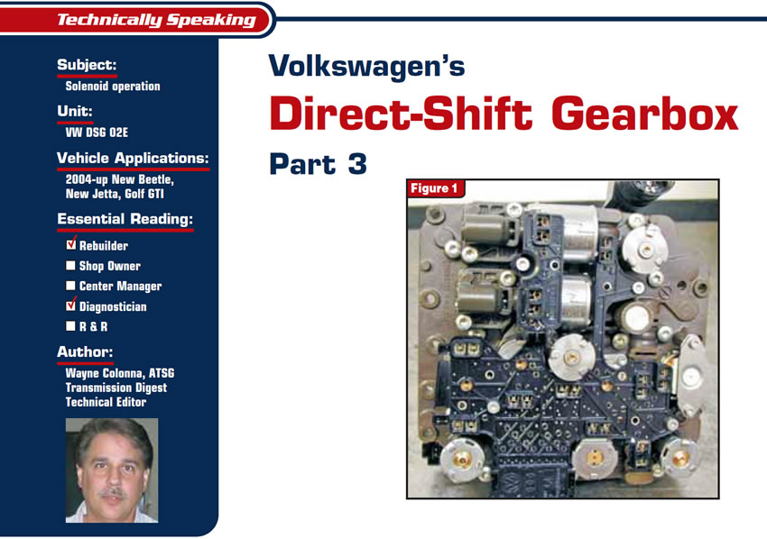
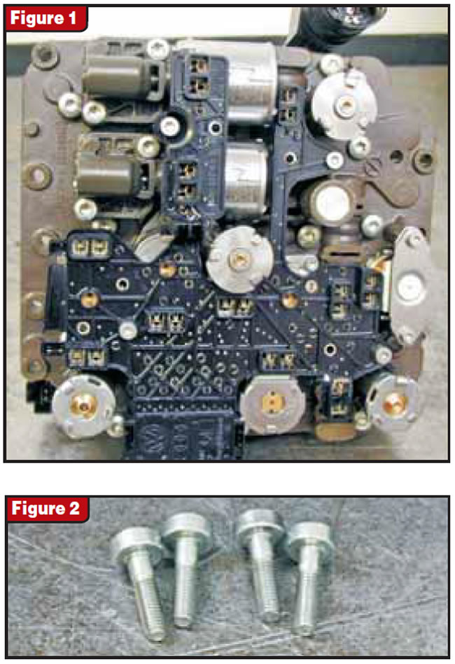
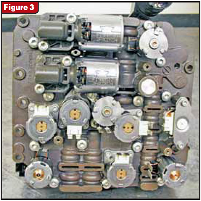
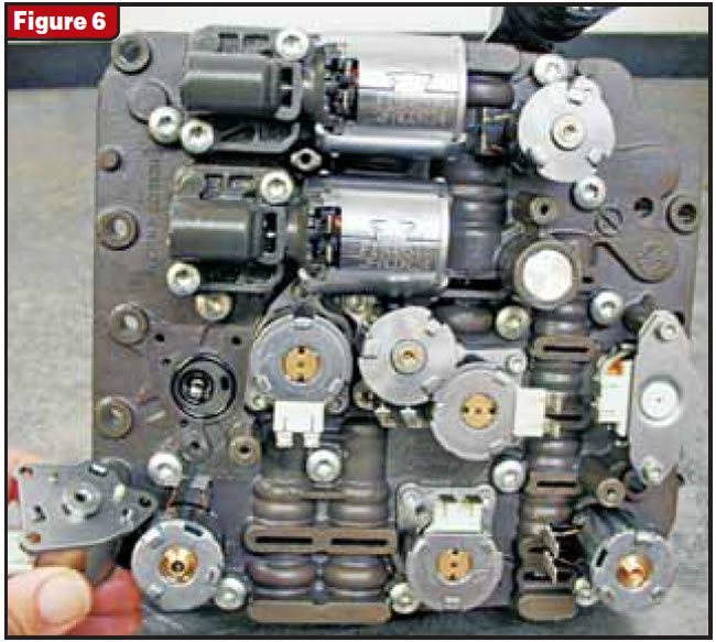
A typical-style conductor plate is used for the solenoid circuitry and is secured to the valve-body Mechatronic assembly with four # 20 Torx-head shoulder bolts that could be easily misused as solenoid attaching bolts (see figures 1 and 2). Once the conductor plate is removed all 11 solenoids come into view (see Figure 3). If you save past issues of Transmission Digest you will find in last month’s issue in Figure 8 a layout that will quickly identify each of these solenoids. I suggest reading it again if you have it, as it will enhance this article greatly.
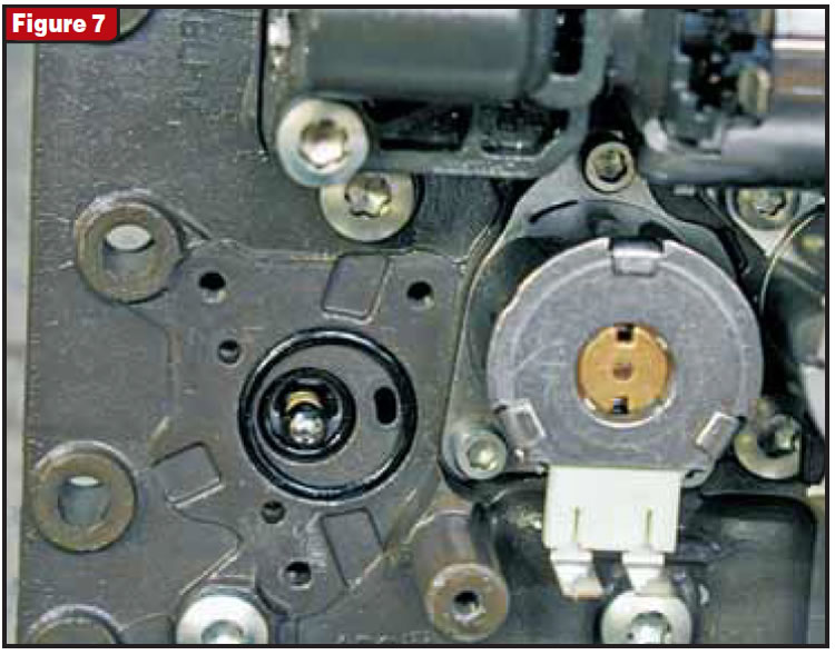
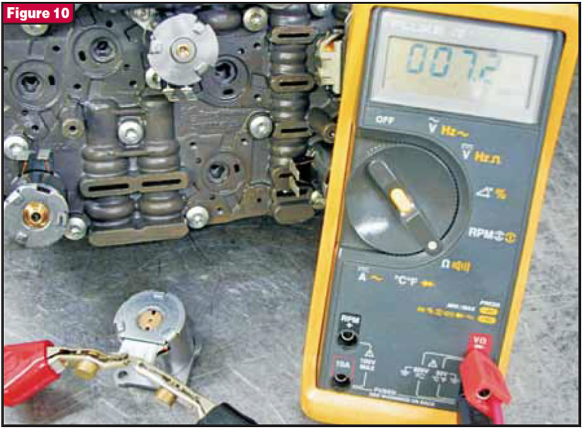
N88, N89, N90 and N91 make up the first group, the gear-actuator solenoids. They are on/off solenoids that measure 7 to 9 ohms and provide one of two gears, depending upon the position of the multiplexer valve in the valve body. You must be careful when removing a gear actuator solenoid, as there is a directional ball seat, a 6mm-diameter checkball, a small five-coil spring and two O-rings under each of them (see figures 4 through 10).
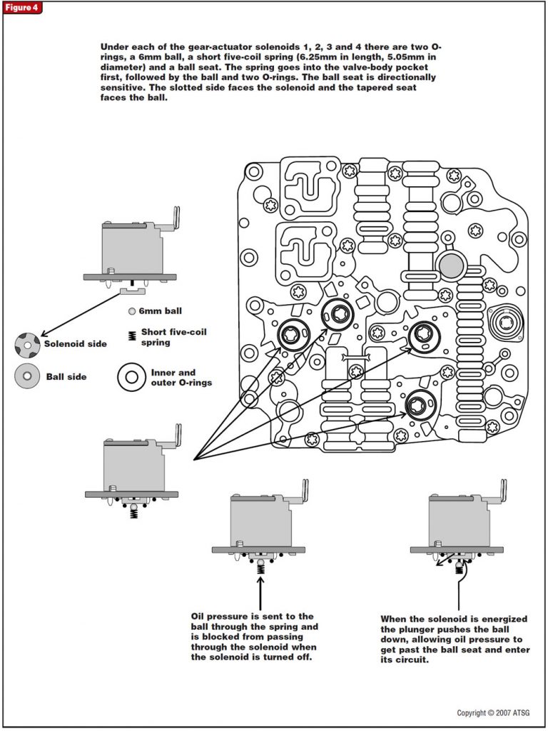
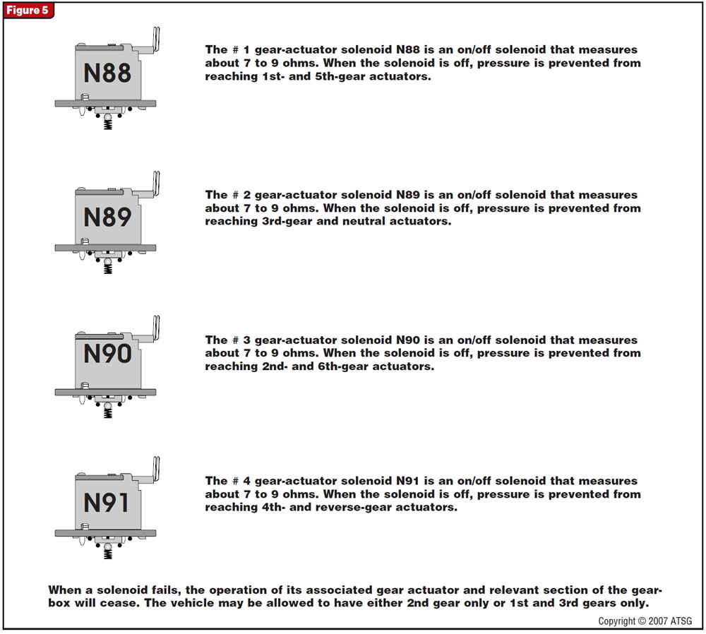
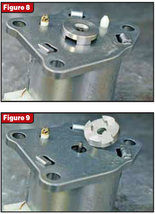
Pressure is supplied to these solenoids from the spring pocket pushing the ball up against the ball seat on the solenoid. When the solenoid is energized, a pushrod in the solenoid extends outward, pushing the ball off its seat. This allows the feed pressure to run around the ball to the back side of the seat and out of its slotted side openings (see Figure 4), where it is then directed to the multiplexer valve and on to its respective gear actuator.
By looking at the operation of this solenoid you can see the importance of the ball seat’s being installed correctly and of having properly sealing O-rings, for they keep the supply and apply circuits separated. It will be interesting to see what could happen when the smaller O-ring leaks, allowing supply pressure into the gear-actuator apply circuit to the multiplexer valve when it should not be there.
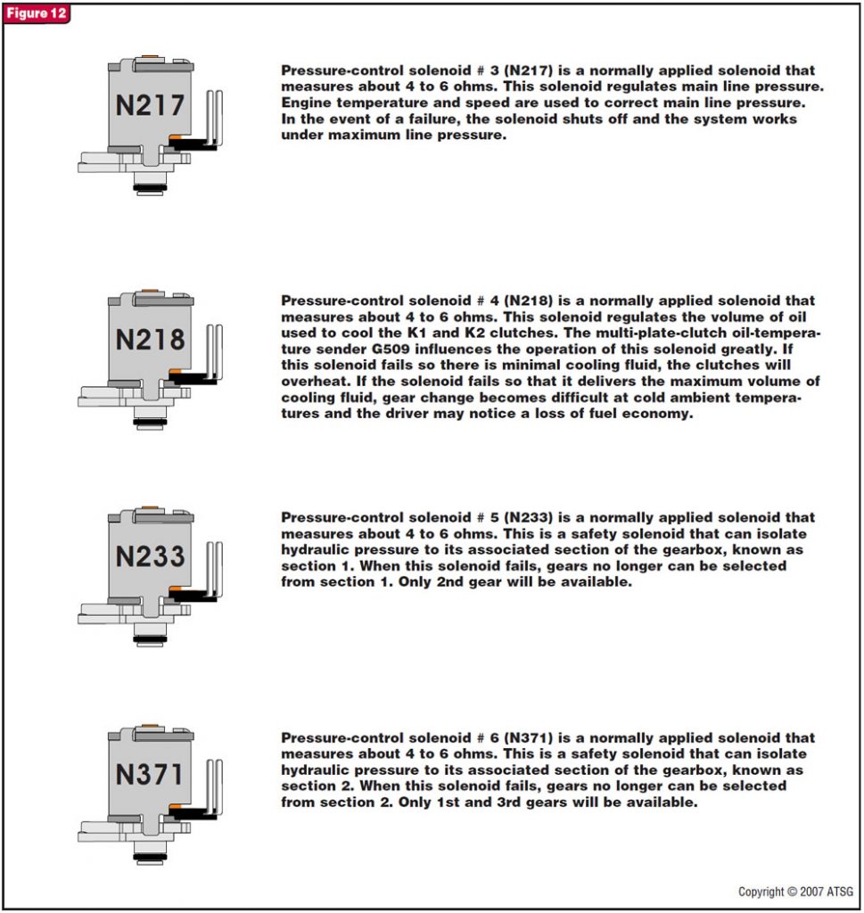
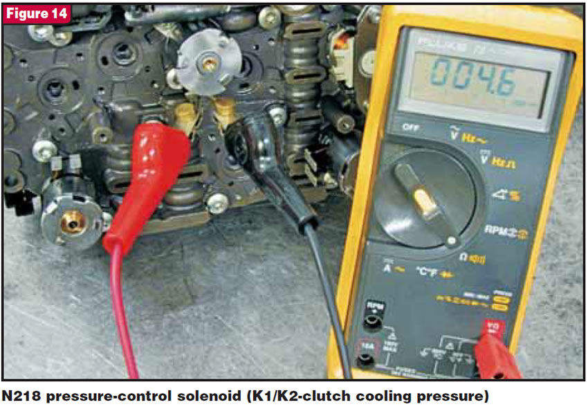
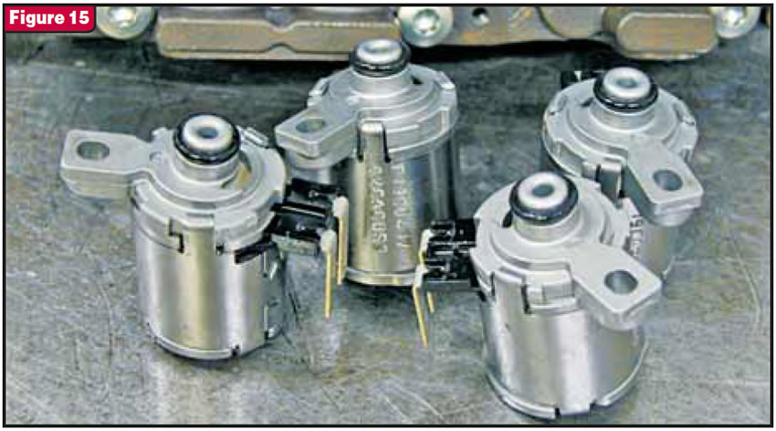
The second grouping consists of six pressure-control solenoids. The four being discussed in this article are N217, N218, N233 and N371 (see figures 11 through 15). N217 is used to control main line pressure, N218 is used to control cooling pressure to the K1 and K2 clutches, and N233 and N371 are safety-control solenoids.
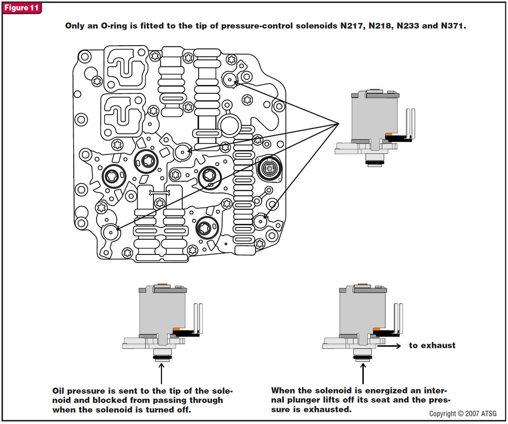
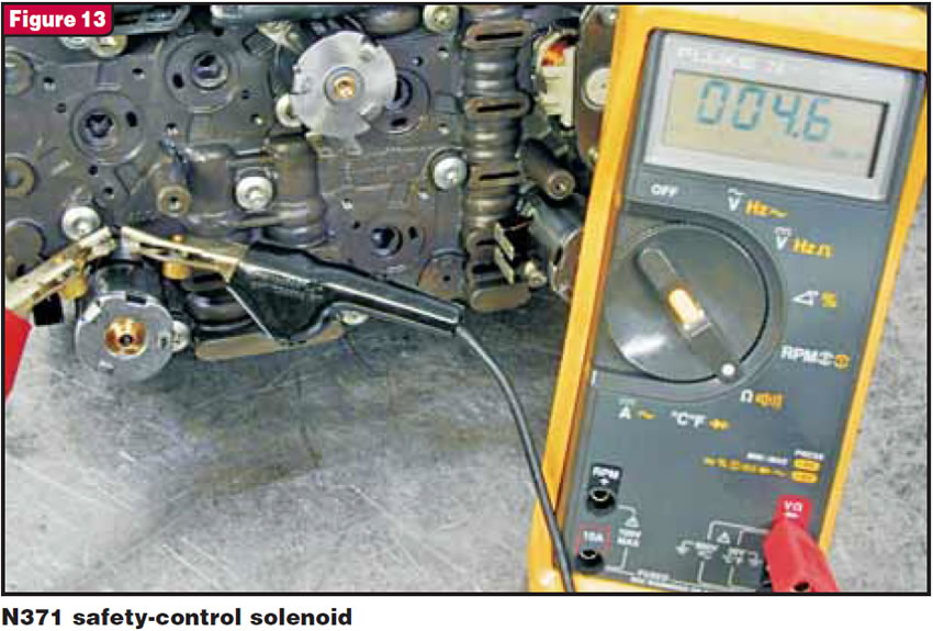
When you look at figures 13 and 14, you will notice that the safety-control solenoid is constructed slightly differently from the pressure-control solenoid, yet they all measure 4 to 6 ohms, they all are normally closed and only one O-ring is fitted to the snout of each (see Figure 15).
Pressure is supplied to the tip of each of these solenoids, and their respective circuits are charged with pressure when the solenoid is off. When the solenoid becomes energized, fluid passes through the solenoid to an exhaust, dropping pressure in their respective circuits (see Figure 11). For a more-detailed explanation of each of these solenoids read the operating details provided in Figure 12. We will finish looking at the remaining solenoids and some helpful box information in part 4 next month.


