Technically Speaking
- Subject: Disassembly procedures
- Unit: VW DSG 02E
- Essential Reading: Rebuilder
- Author: Wayne Colonna, ATSG, Transmission Digest Technical Editor
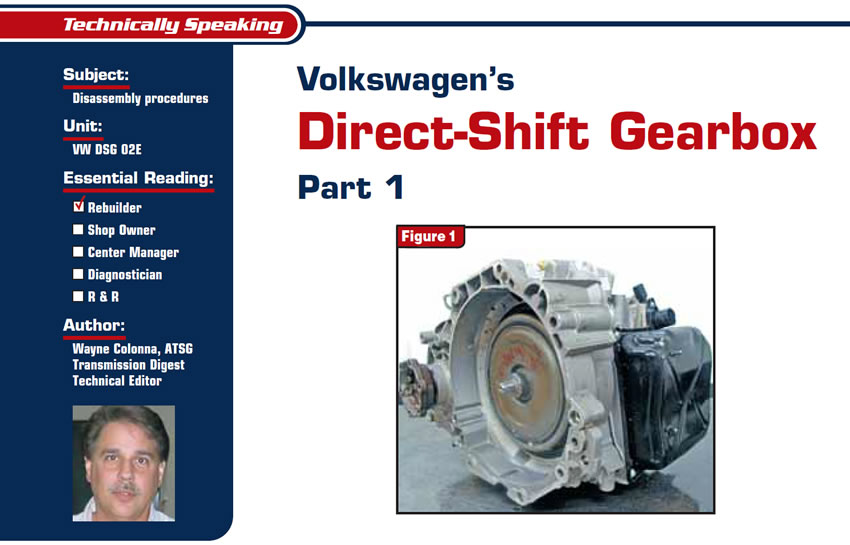
Volkswagen’s direct-shift gearbox DSG 02E (see Figure 1) is used in the United States in some 2004-to-present New Beetle, New Jetta and Golf GTI models. It is a six-speed manual front-wheel-drive gearbox that is shifted automatically.
This unit uses two clutch packs, called the K1 and K2, to drive two input shafts called no other than input shaft 1 and input shaft 2. Each input shaft has its own set of gears that drive output shaft 1 and output shaft 2. (I’ll bet you saw that one coming!) This article begins with a few tips on tearing the unit down, and following articles will get into how it works.
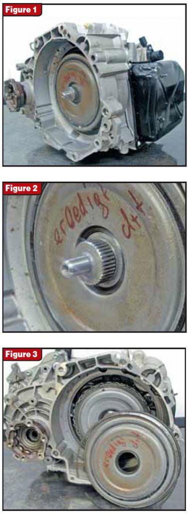
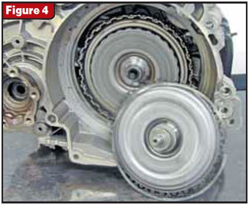
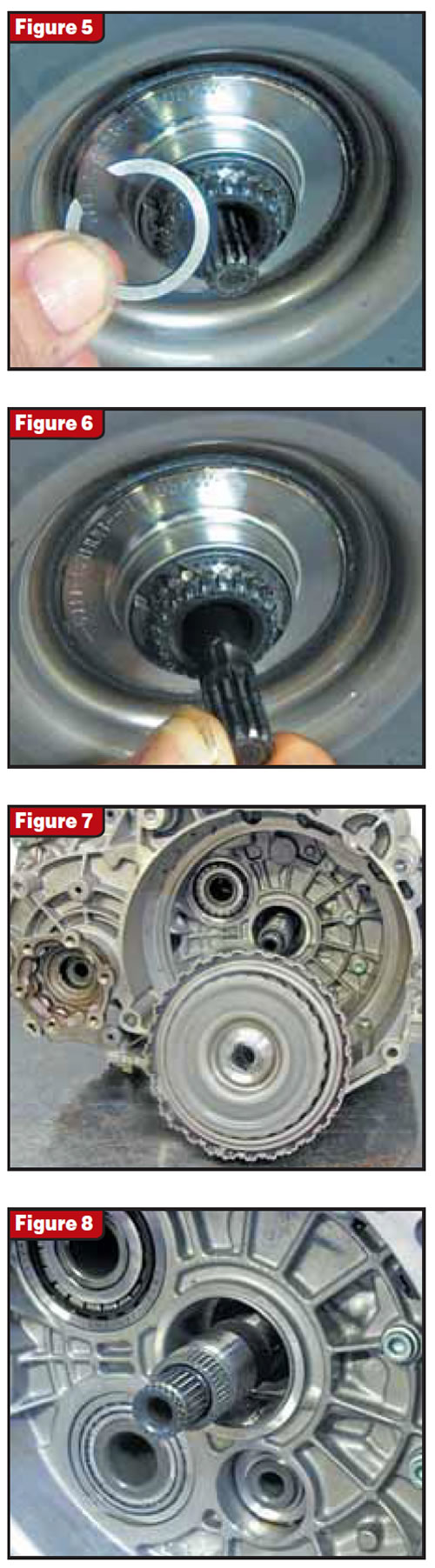
A closer look at the front of the unit shows a large piloted input shaft that is driven by a dual-mass flywheel (see Figure 2). The front of the transmission is sealed with a molded cover plate held into the transmission with inner and outer snap rings (see Figure 3). This molded cover plate is similar to what is used in 45RFE units covering the pump. The cover plate in this DSG transmission seals oil that is used to cool the K1 and K2 clutches as they are simultaneously pulsed on and off during shifts. After removing the cover plate, you can see the whole clutch housing with the large piloted input shaft (see Figure 4). This cover is held into the housing with a snap ring, and when it is removed the K1 and K2 drum assembly is visible along with a pump-drive shaft.
A snap ring holds the K1/K2 clutch drum onto the double input shaft. After you remove the snap ring and pump-drive shaft the drum assembly will slide off the input shafts (see figures 5 through 8). The longer of the two shafts is input shaft 1 and the shorter is input shaft 2.
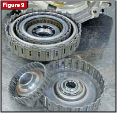
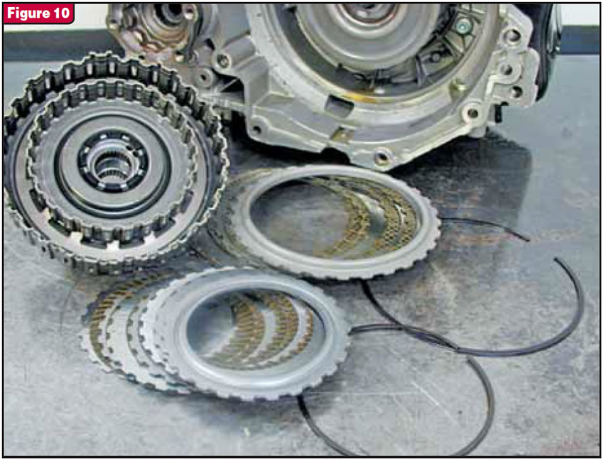
Figures 9 and 10 show the K1 and K2 clutch drum partially disassembled. The larger outer clutches are the K1 clutch, which drives input shaft 1, and the smaller clutches are the K2, which drives input shaft 2.
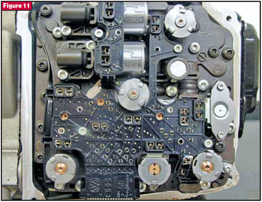
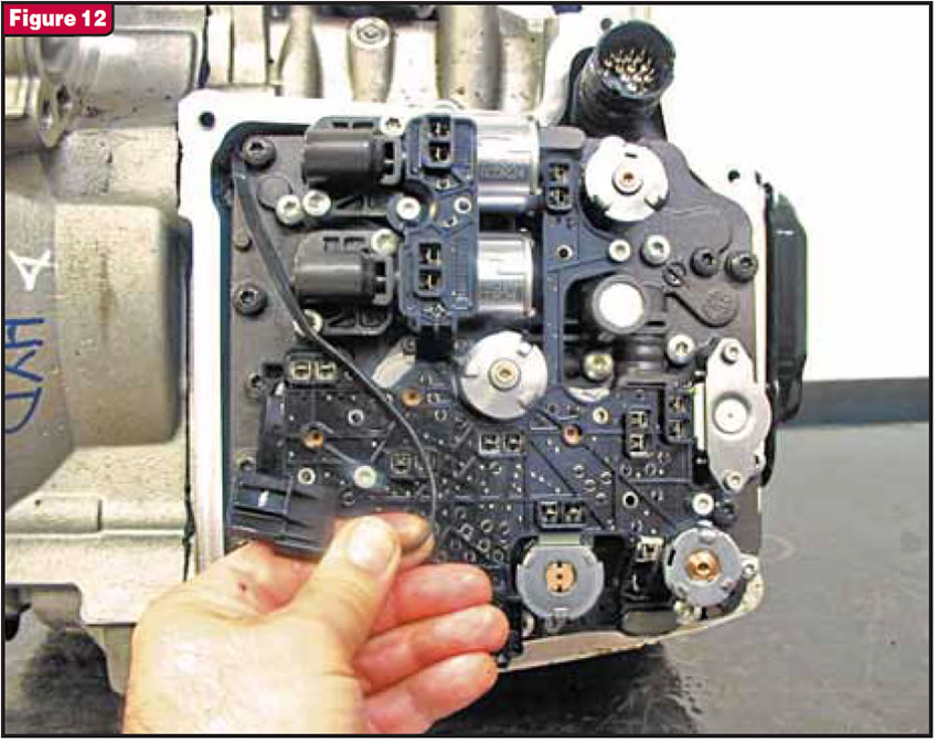
With the side pan removed you will find that there is a valve body with 11 solenoids and the transmission’s computer (see Figure 11). Before removing the valve body you will need to do a couple of things. The first is to remove a ribbon wire from a clip retainer and unplug it from the computer (see Figure 12). Then you need to remove nine #30 black-head Torx bolts. It may be a good idea to give them each a sharp tap before removing them as the Torx pocket is shallow and can easily strip out.
Once the bolts are removed, carefully pull the valve body and TCM assembly off the transmission. And I say carefully because there is a long double output-speed-sensor pickup integral to the TCM that could be snapped off if you are unaware of it (see Figure 13). You may tend to use this long sensor pickup as a handle to move the assembly around – not a good idea!
With the TCM and valve body out of the way, the sensor previously unplugged can be removed from the case (see Figure 14). This item contains an input-speed sensor and an oil-temperature sensor. The oil-temperature sensor monitors the temperature of the K1/K2-clutch cooling oil. This input to the TCM allows the computer to control the flow of cooler oil through one of the 11 solenoids on the valve body. The input-speed sensor is used to calculate clutch slip. The engine-speed sensor is used as a backup should this sensor fail.
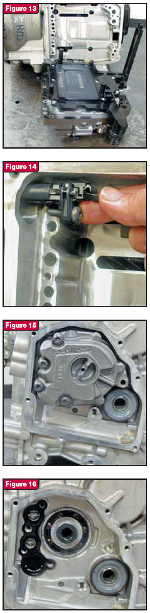
On the back side of the transmission is a small back cover that you can remove to gain access to the pump (see Figure 15). With the pump removed you will find a sensor wheel on the back side of output shaft 2 (see Figure 16). This is the sensor wheel that is used to excite the two Hall-effect output sensors in that long extension on the TCM. The use of two output-speed sensors allows the TCM not only to know the speed of the vehicle but also to determine whether it is moving forward or reverse. The wheel-speed sensors for the ABS serve as a backup should these sensors fail.
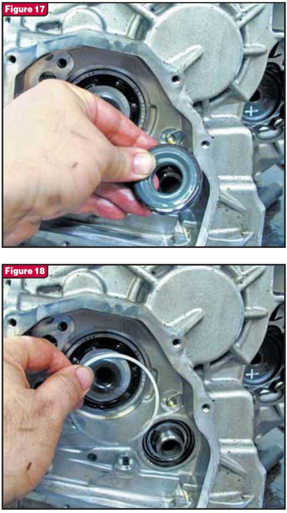
Be careful not to deform the sensor wheel during removal or you will have to find another (see Figure 17). Once you remove the wheel there is a snap ring that you will need to remove (see Figure 18).
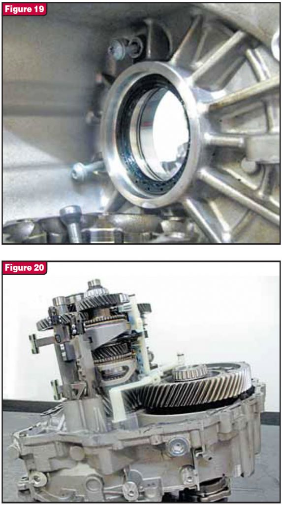
The axle flanges are held into the differential with allen screws and will need to be removed. You also will find two bolts in the case after removing the inside axle flange (see Figure 19). You absolutely have to remove these bolts before splitting the case or you will destroy the internal plastic lubrication plumbing assembly. This, I assure you, will not make your day. The next step is to remove the external cooler on top of the transmission and remove 22 case-to-cover bolts with a #8 star Torx socket. After you are finished you can carefully and safely separate the case halves (see Figure 20).
I will be back next month with Part 2 of the DSG 02E.


