Technically Speaking
- Author: Wayne Colonna, Technical Editor
The Toyota Prius P111 hybrid transaxle shown in Figure 1 is a continuously variable transaxle. If you are already familiar with a Subaru Legacy or a Honda Civic HX, you might think this is another CVT with a belt and pulleys. Not this unit.
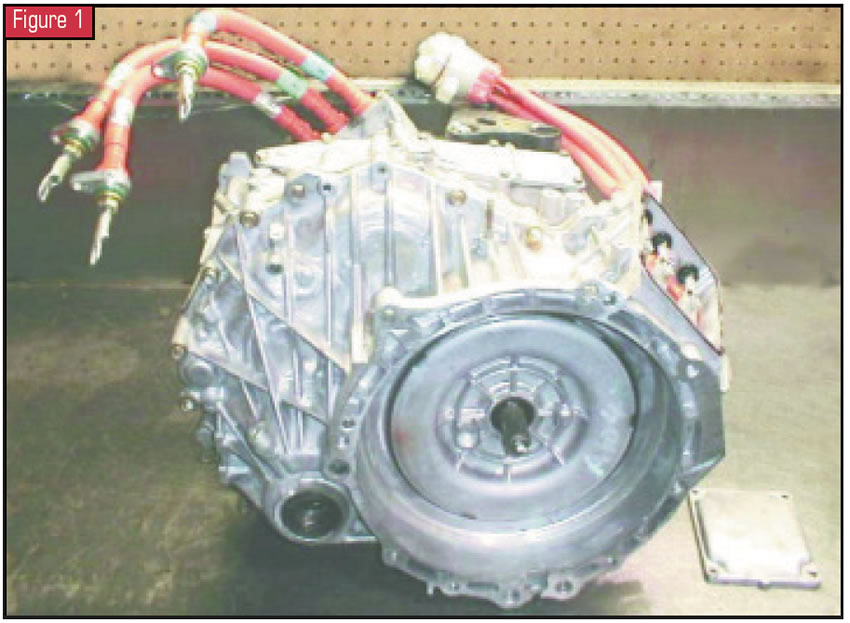
The “continuously variable” in this transaxle is achieved through a power-split device familiarly known as a simple compound planetary gearset as well as motor generators 1 and 2 (MG1 and MG2). It is through these motor generators and the planetary gearset that the continuously variable ratios occur. At times this planetary assembly is used to drive the vehicle, charge the high-voltage battery or both; hence, the name “power-split device.”
Let’s get inside this unit and start looking at some of these parts. We will begin with the removal of the high-voltage cables from the transaxle. Figure 2 shows the cables that connect to motor generator 1. The other end is where these cables connect to the inverter (See Figure 3). You also can see in Figure 2 the other three high-voltage cables that go from MG2 to the inverter.
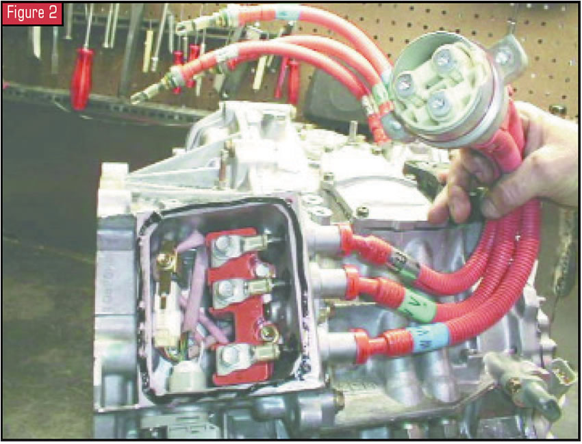
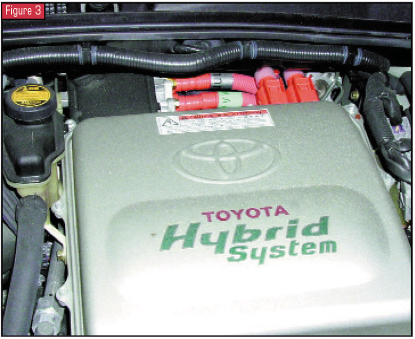
The inverter is a very busy electrical-power converter. It converts electrical power between the 273.6-volt DC battery and the three-phase alternating-current (AC) voltage from the two motor generators in the transaxle. It also transmits information to a computer called the high-voltage electronic control unit (HVECU).
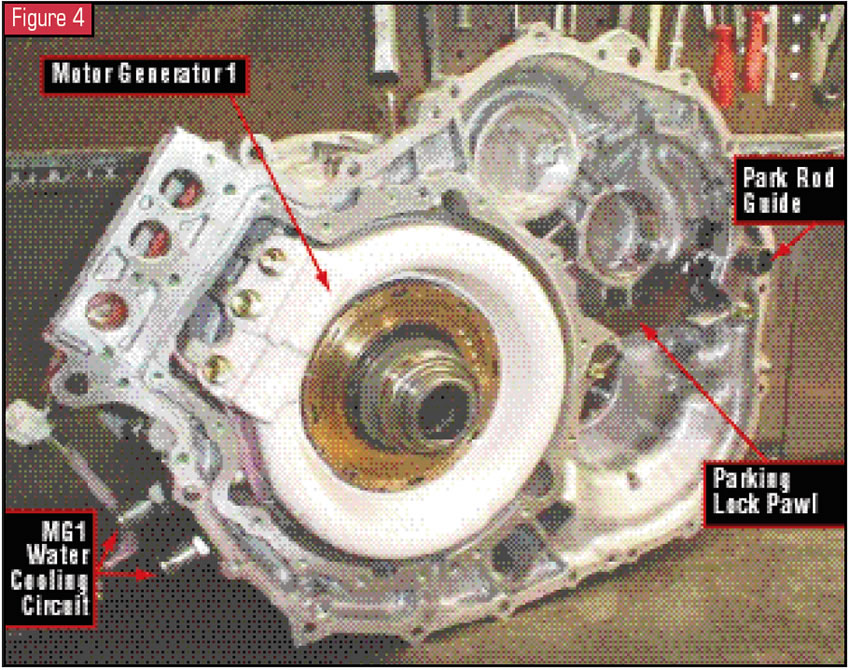
With the case split, you can see the back side of the “bellhousing,” where motor generator 1 is (see Figure 4). Inside the engine side of the “bellhousing” is a coil-spring damper assembly designed to absorb torque fluctuation between the engine and transmission.
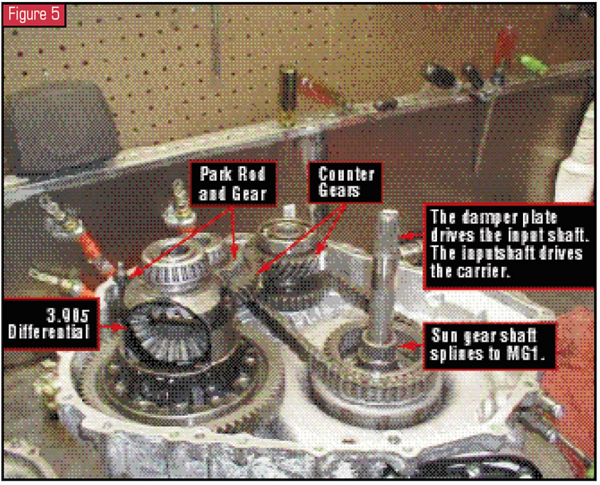
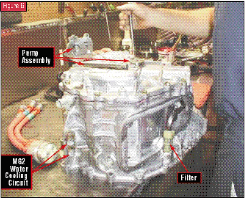
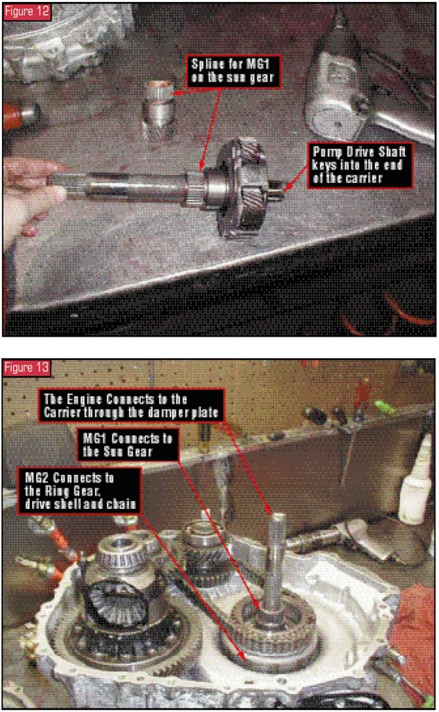
The pan, a pump, the geartrain and motor generator 2 are in the rear half of the case (see Figure 5). This transaxle has what is called a trochoid pump that is used for a force-feed lubrication system only. The pump is driven directly by the engine through the planetary carrier, to which the pump driveshaft is splined. This pump lubricates the transmission and final drive from the fluid it draws out of a common sump arrangement through a tube filter in the pan (see Figure 6).
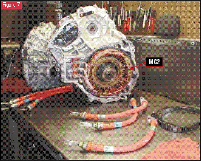
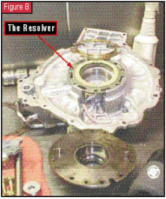
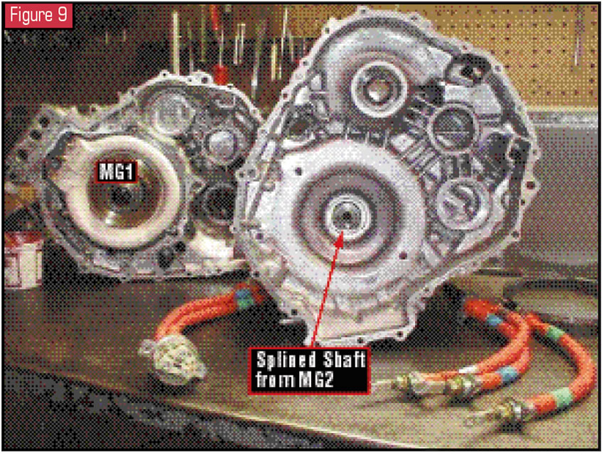
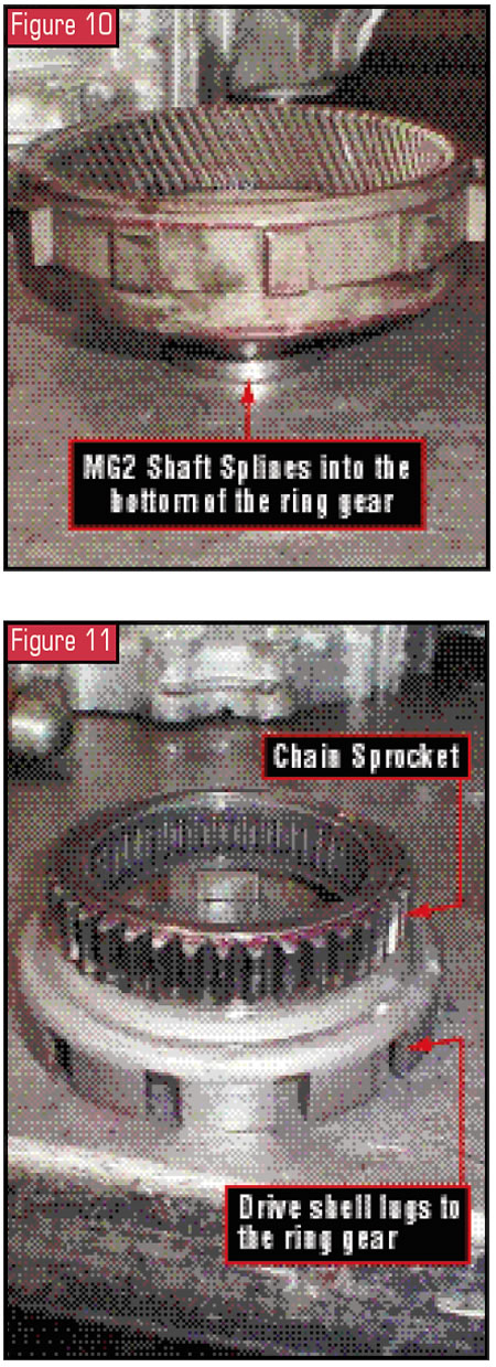
When the back cover of the rear case half is removed, MG2 is visible (see Figure 7). Inside the back cover is a speed-sensor ring called a “resolver” (see Figure 8). Figure 9 shows the empty case flipped around to reveal the splined shaft driven by MG2. This MG2 shaft splines into the ring gear (see Figure 10). The ring gear then lugs to the drive shell and chain sprocket (see Figure 11).
OK, now that we have had a chance to see some of the parts, let’s do a review.
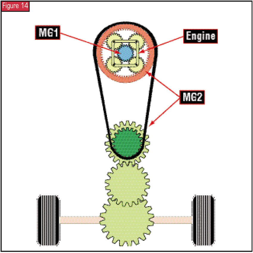
The engine, when running, drives the planetary carrier through a damper plate, which also drives the pump through its own driveshaft (see Figure 12). The sun gear is connected to MG1, and MG2 is connected to and drives the ring gear. The ring gear is lugged to a drive shell and chain sprocket (see Figure 13). The chain drives the differential through the counter gears, and the differential drives the front wheels. In short, MG2 always drives the tires except during deceleration; then, the tires are driving MG2, which in turn is generating electricity to be stored in the hybrid-vehicle (HV) battery. So if the vehicle is moving forward or backward under power, MG2 is driving the tires (see Figure 14). It is during normal and full acceleration that the gasoline engine assists MG2 in driving the wheels through the power-split device.
MG1 in this transaxle is used to recharge the HV battery and supply electrical power to MG2. It also regulates the amount of electrical power supplied to MG2 through the inverter, which varies MG2’s speed, effectively controlling the continuously variable ratio function of the transaxle. The only time MG1 drives the sun gear is when it is used to start the engine. Otherwise, the planetary drives the sun gear, and that makes MG1 generate electricity.
It is a little challenging to understand the operation of this planetary assembly as a power-split device, because as transmission technicians, we’ve always thought of torque as starting with the engine and being delivered to the drive tires through a transmission. We had never had to consider multiple sources of torque, multiple destinations for torque or all of these occurring simultaneously – especially through a simple compound planetary gearset.
Another point to consider is that we also are accustomed to one member of a planetary system being held stationary while another is a drive member, making the third a driven member. In the power-split device, a holding member could mean a resistance hold or a variable hold, and a driving member can be driven at variable speeds.
Let’s look at what occurs during a light-throttle take-off. The gasoline engine is not running; the HVECU commands MG1 to be ineffective while the HV battery is powering MG2 to drive the wheels. This means that as MG2 is driving the wheels, the internal ring gear in the planetary system also is being driven. Since the engine is not running, the planetary carrier is not moving. The internal ring gear drives the pinions in the carrier. Since MG1 is ineffective, the pinions drive the sun gear in the opposite direction. Simply stated, during light-throttle take-off, MG2 is doing all the work to move the vehicle while the pinions and sun gear go for a free ride. Although the sun gear is spinning freely, MG1 is not producing electricity.
Now the driver tips in the throttle to reach a normal drive speed. MG1 drags the sun gear. This action forces the pinions, which are being driven by the ring gear, to walk around the sun gear, which rotates the carrier. The carrier’s rotation starts the engine. Now that the engine is running, it becomes an input to the carrier, which then drives the sun gear. This input force then is divided within the planetary gears. A portion of it is used to help MG2 drive the wheels, and the rest is used to drive MG1 for generating electricity. This same principle of operation occurs during full-throttle acceleration – with one addition: The power stored in the HV battery further supplements the drive power of MG2.
When the selector lever is placed into reverse, the HVECU sends this signal to the inverter. The inverter changes the phase angle to MG2, which then rotates in the opposite direction, driving the wheels in reverse. If the state of charge (SOC) of the HV battery exceeds the specified value, only MG2 operates. If the SOC drops below its limits, MG1 drags the sun gear, causing the carrier to start the engine. The engine runs up to a speed high enough to spin the sun gear so that MG1 can generate electricity. This then passes through the inverter to be used in assisting MG2 in driving the wheels in a reverse rotation. This is a great example of how the planetary becomes a power-split device – the increase in engine speed did not alter the speed of the vehicle.
This same principle also occurs during normal driving conditions. As you are driving, you may suddenly notice an increase in engine speed without stepping into the throttle. This occurs when the HV battery has dropped below the SOC limit. The planetary will allow the engine to increase to the speed needed to drive the sun gear, causing MG1 to generate charging voltage without affecting the road speed of the vehicle.
When I was speaking with technician David T. Uncapher from Kendall Toyota, he noted that when he first drove this vehicle, he drove it like a mechanic trying to “feel” the car.
“It was an odd feeling driving a car that didn’t function like any car I ever drove,” he said. “When I decided to just drive the car with the A/C and radio on and not pay attention to the “feel” of the car, it drove like a car. It did everything I asked it to do.”
And that is exactly how to describe it. It is not going to feel like the cars we are used to driving, because it doesn’t operate like a typical car. It is a hybrid vehicle, and because of that, the throttle position may have a direct effect on vehicle speed without having any direct effect on the engine speed. Hmmm – could that be why the fuel consumption and emissions are so low?
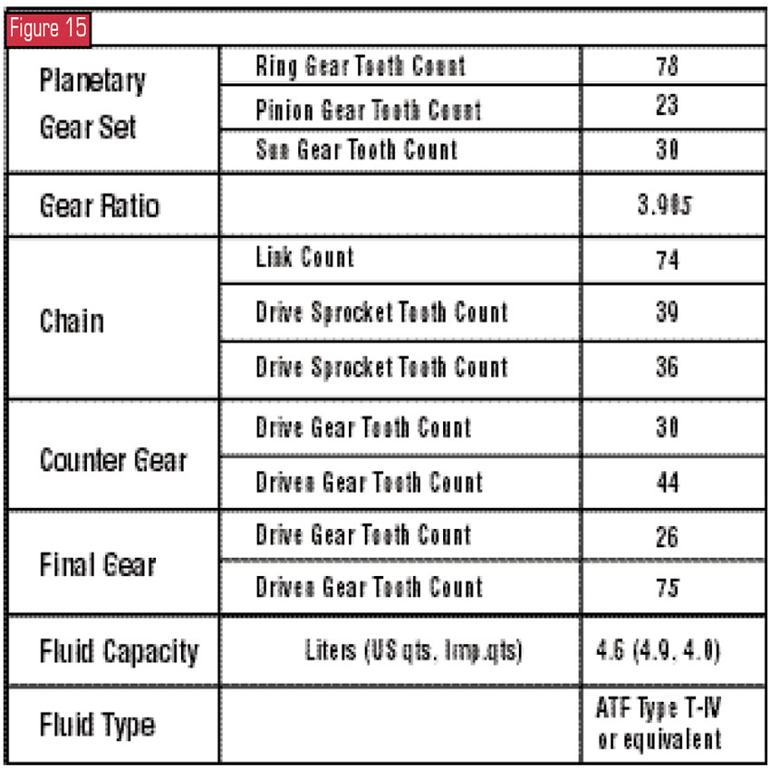
For additional P111 specifications, refer to Figure 15.
Once more, I thank Frank Kuperman from Phoenix Remanufactured Trans, who supplied me with the photos of the transaxle to make this article possible.