

The vast majority of time that is spent in a transmission shop is devoted to diagnosing and repairing automatic and manual transmissions for cars and trucks. The vehicles range from small to large, usually with one common characteristic: four wheels.
Occasionally, a shop may work on an uncommon transmission type such as a marine or tractor transmission or some other off-highway application. Aggressive shops are always on the lookout for new stuff to do.
Any time a reference is made concerning a three-wheeler, visions of a motorcycle or ATV come to light. Three-wheeler police “sickles” have been around forever, and even a fair number are owned by the public. But they are, after all, motorcycles, and most transmission shops draw the line at repairing motorcycle transmissions.
There are, however, different kinds of contraptions (vehicles) on the road today that have three wheels but are not like motorcycles. As with most other modes of transportation, there has been an evolution within the three-wheel-vehicle population.
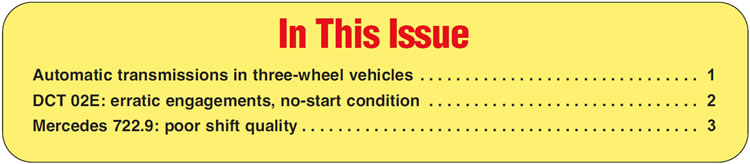
The three-wheel vehicles in use today are a little more sophisticated than a golf cart (Figure 1). Instead of having a Briggs & Stratton lawnmower engine, many of the newer three-wheelers have real (although small) engines equal to that of a small car.
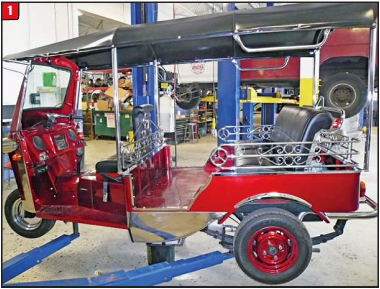
The engine in the illustrated three-wheeler is a 0.6-liter with fuel injection. Beyond the engine is a regular powertrain that consists of a transmission, drive- shaft and differential (Figure 2). The game is ratcheting up.
Development of three-wheel vehicles has occurred not in the U.S. but in other countries around the world. Due to resources, fuel cost, population etc., several countries were forced into having these smaller modes of transportation. Countries like Japan and India have dealt with this issue for decades.
The three-wheeler shown in Figure 1 was actually produced in Thailand and is called a “Tuk Tuk,” pronounced “took, took.” The vehicles initially were provided with two-cycle engines, but as pollution got worse many were switched over to four-cycle engines. The Tuk Tuks have been exported to several countries over the years and are a growing trend.
A common three-wheel vehicle in the U.S. is one used by meter maids around the country and is produced in Canada by a company called Westward Industries under the brand name GO-4 Interceptor. The engine in the GO-4 is a three-cylinder 69-horse-power design and uses the JF405E four-speed automatic produced by Jatco. The JF405E is used in cars by Suzuki and Nissan and has been for some time.
The Tuk Tuk, also referred to as an auto rickshaw, originally was imported from Thailand with four-cycle engines, but because of changing EPA regulations, importation of the vehicle with the gas engine was stopped. Recently, a U.S. company started to produce the Tuk Tuk in the states using electric propulsion with the Thailand chassis. Other areas of the world have been switching over to CNG- or LPG-type gas engines.
The transmission used in the illustration was actually produced by Daihatsu and is currently being used by Daihatsu and Toyota in several small car models around the world. The model name is the A3S, which is RWD, and there is a FWD version called A3LB1. These three-speeds are being used into 2010 and 2011.
In an age of computer-controlled eight- and nine-speed automatics with countless solenoids and sensors, itʼs comforting to know there are still some basic, simple boxes around to wrench on.
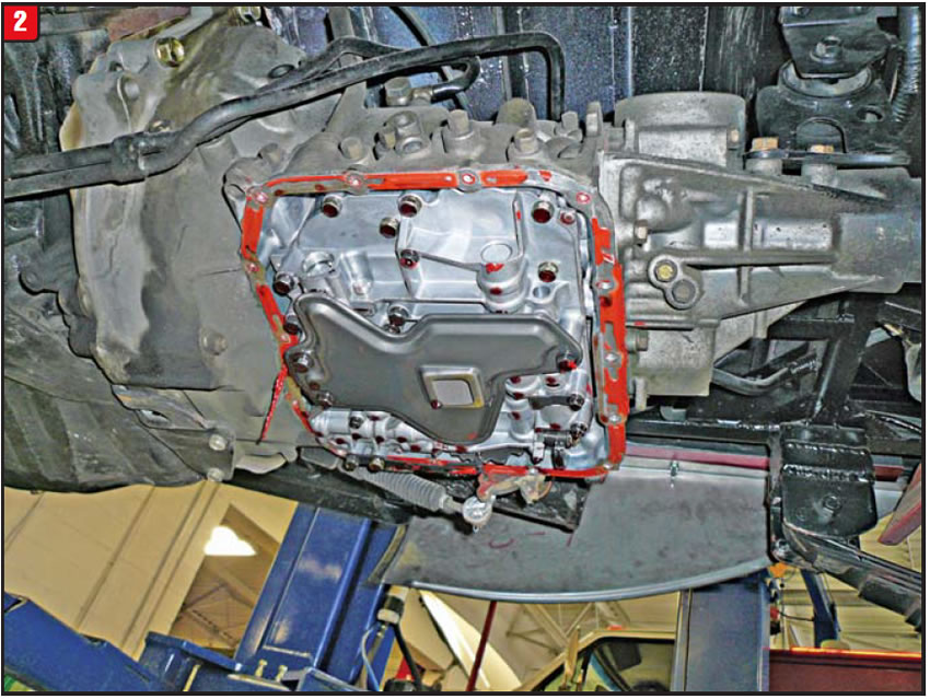
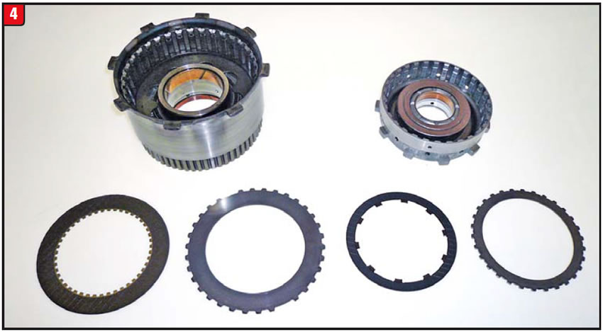
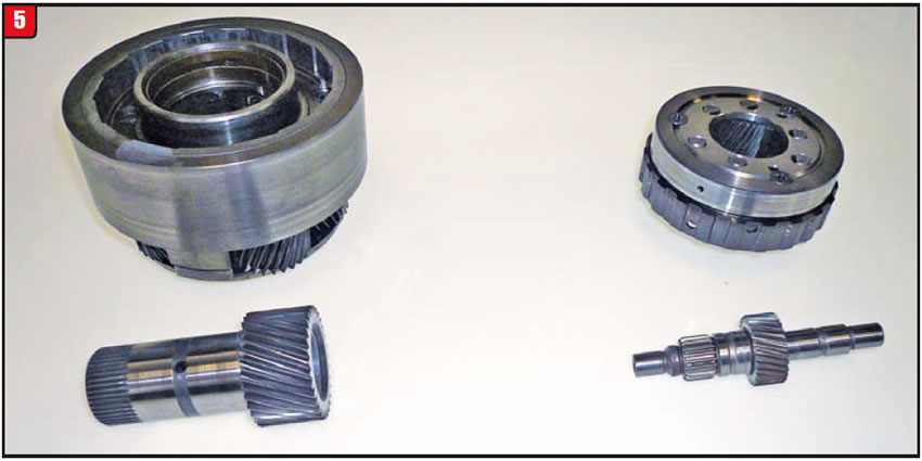
The following photos illustrate the difference between the A3S and a regular RWD transmission. Components in each illustration are from the A3S and 4R70W, just to provide a sense of scale.
The first component illustration (Figure 3) is of the pump body. The one on the left is from the 4R70W (of course). Even though they are both gerotor pumps, the A3S is still in puberty.
The illustration in Figure 4 is that of the reverse-clutch drum along with a friction and steel. The A3S frictions and steels look more suited to a go-cart or snowmobile.
The planetaries in Figure 5 are both compound-planet designs using forward and reverse sun gears. The reverse sun gear and shell (not illustrated) for the 4R70W are welded together, whereas they are splined together on the A3S and can strip out. The A3S also uses a one-way clutch (OWC).
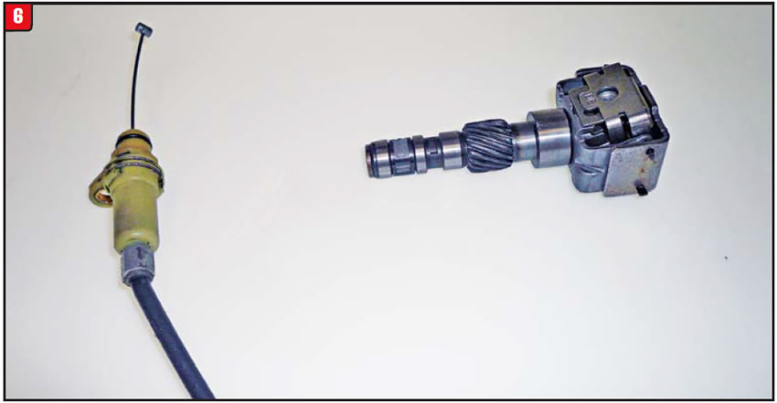
For technicians who have recently joined the transmission-repair industry, the items in Figure 6 may be unrecognizable. Thatʼs because the two components have gone the way of the dodo bird. The thing on the right is a governor, which provides road signal to the valve body, and the item on the left is the throttle cable to signal pedal position. Old-time technology still lives on.
In conclusion, the next time the phone rings and a potential customer refers to a three-wheel vehicle instead of four, donʼt just assume itʼs a Harley.


A 2006 Volkswagen Jetta equipped with an 02E DCT experiences not only erratic-engagement issues but, at times, a no-start condition as well. The VW name for this transmission is a DSG (Direct Shift Gearbox).
In addition to the engagement and start issues, the indicator light cluster blinks. The PRNDL dash lights blink on and off when the malfunctions occur. Diagnostic trouble codes that appear are P0600 and P1626.
The transmission can at any time lose apply (go into neutral) and not have any engagement, drive or reverse. In addition, if the shifter is placed into park during this episode, it will not come back out. Wait just a bit with the engine off and everything returns to normal. Getting stuck in park out on the highway is not a treat, even for a short time.

Although ultimately the shifter control module proved to be the culprit, other components can also contribute to these kinds of conditions. Having the proper diagnostic equipment is a real benefit when dealing with this type of vehicle and transmission.

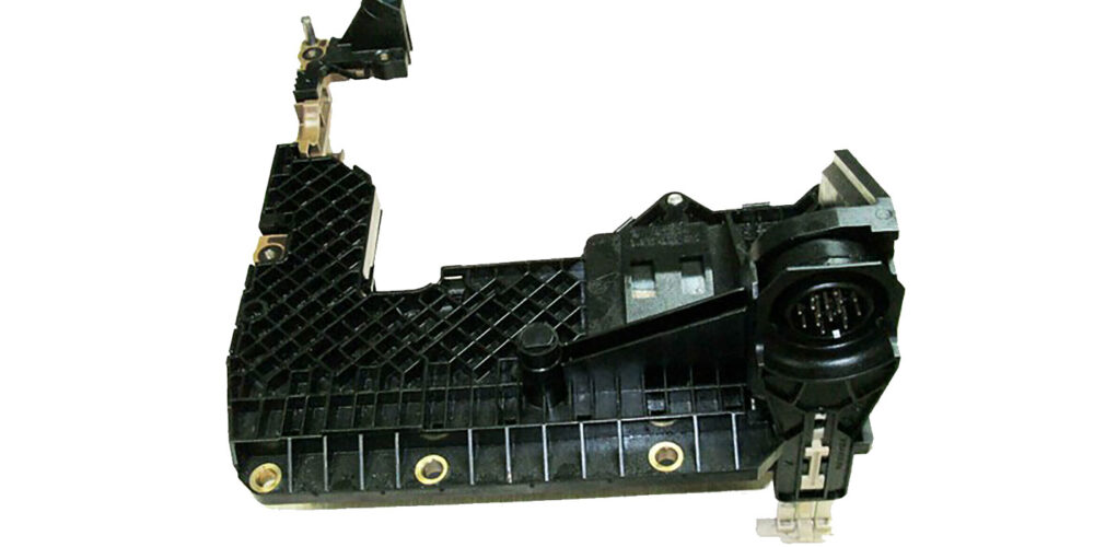
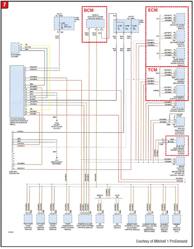
The 02E DCT (dual-clutch transmission) is basically a “stick” that has been automated. It has traditional standard-transmission gears, synchronizers, shafts and forks. In addition, it has a dual-clutch assembly, oil pump and filter, sensors and a mechatronic valve body, just like a regular automatic. Operation is also automatic in nature, requiring all the normal external controls (Figure 7).
Before disassembling anything, it is advisable to connect a laptop with a VAG program to test for codes and specific operations. If the VAG indicates a loss of connection with the transmission, then start to wrench.
This vehicle has various modules to control a variety of functions such as doors, heater and AC, air bags etc.; however, the main components affecting transmission operation are the ECM, TCM (with valve body), shifter control module and harnesses.
Unlike a regular transmission, which has an external TCM, a unit with a mechatronic valve body has computer lines (data stream) going directly to the transmissionʼs electrical connector. The bulk of the wires that are wired to the connector plug are regular power or ground wires, but the two that carry computer data stream are the orange/black (terminal 10) and the orange/brown (terminal 15) wires (Figure 8).
To determine the cause of the complaints listed requires a process of elimination. The initial question to ask is, “Is the problem internal or external?” The key items to check are the shifter control module, harness wires, connections and the TCM.
The shifter control module is accessible under the center console. After removal of the ashtray and shifter boot, the harness becomes visible along with the park-lock solenoid and module. The connections can be inspected along with the wiring. An ohmmeter can be used to test the harness from the shifter to the transmission.
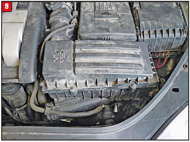
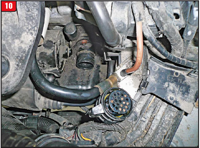
To gain access to the transmission connector requires popping the hood. Unfortunately, there is a fair amount of debris to remove to gain access to the transmission (Figure 9). Once all the air-cleaner stuff is removed, the transmission electrical connector will be visible, but somewhat under the starter. The external case-connector harness plug does not just pull off. It has a locking sleeve that must be rotated just like in the Mercedes 722.6 transmission.
Unlike a GM electrical-harness plug or connector, which has letters to denote pin position, the 02E has none (Figure 10). Wire-color code becomes really important when youʼre trying to diagnose.
Refer to the wire-color code in Figure 8 and use a regular V/O/A meter to check the power and ground terminals. Hook up an oscilloscope or similar tester and check the two data-stream wires (orange/black and orange/brown) for any kind of signal wave. This procedure will at least establish whether the harness connections are good.
There are designated testers available, such as one from BlueReach Automation, that can better test computer data signal and TCMs. It is certainly worth the investment because of an increase in transmissions with mechatronic systems (TEHCM = transmission electronic hydraulic control module).
Assuming that the shifter control module and harnesses check out, the next thing to focus on is the valve body. Removing the valve body in the vehicle can be a challenge because of limited space and valve-body design. Test everything possible before going through the drill.
The TCM plate is detachable from the valve body and has the case connector, speed sensors, gear-select sensors and TCM included. Use caution handling the TCM to avoid static discharge and especially output-sensor breakage (Figure 11).
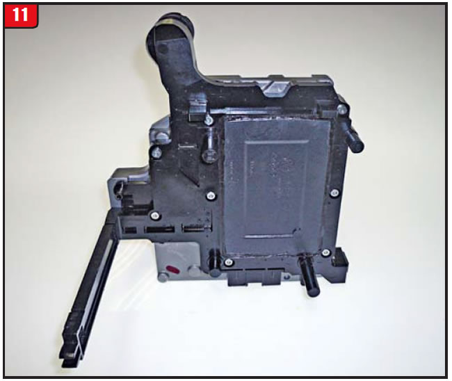
There are companies that are starting to recondition TCMs, but it can take some time for turnaround and itʼs not inexpensive either.
The valve body itself is like most valve bodies except for the 11 solenoids that are attached (Figure 12). Although the TCM operates with a computer data-stream signal, all solenoids function normally using power and ground signals. Solenoid resistance does vary between specific solenoid types, so verify the types with an ohmmeter.
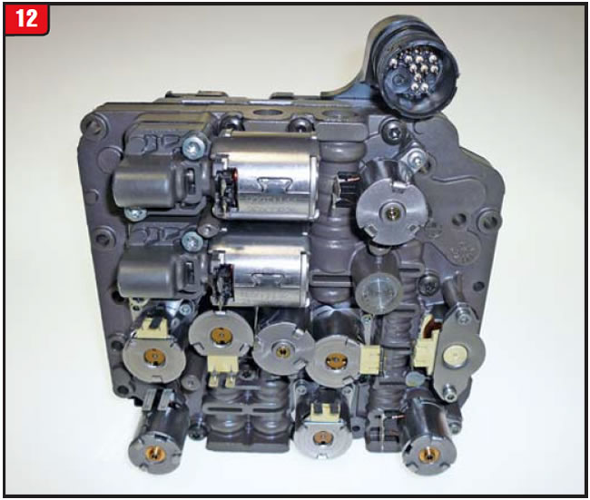
An individual solenoid would not cause the complaints listed in this article but sure could cause other problems.
In the end, knowing the system and having the proper testers is the key to diagnosing a transmission like the 02E, especially when it wonʼt come out of park.


A Mercedes 722.9 transmission exhibits poor-quality 1-2/2-1 or 3-2 shifts prior to or after rebuilding of the transmission. The complaint may be erratic or constant.
There are two different possibilities that can contribute to the shift complaints mentioned. One has to do with computer shift strategy while the other has to do with B1- or B3-brake clutch-pack clearances or apply issues.
Unlike the 722.6 transmission family, 722.9 models are mechatronic, which means even more diagnostic woes. In addition to the TCM being integral with the valve body, the 722.9 also has adaptive learn capabilities.
If the apply parameters are exceeded then obviously the TCM will go into overload, which can impact all shift functions. Before any internal repair is attempted, the vehicle should be driven with a qualified tester attached.
Initially, road-test the vehicle and record the shift-adapt readings using a variety of throttle openings. Then, reflash the system and drive it again to determine whether the condition has improved. If the mechanical stuff is in order, all shift quality should be acceptable. If shift quality does not improve, then go to “Plan B.”
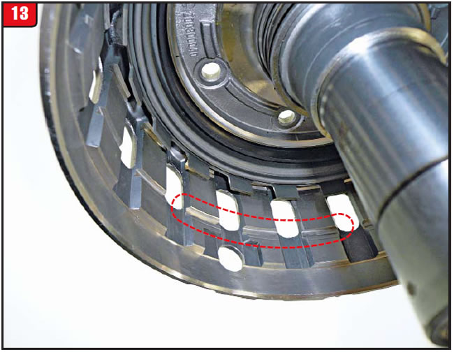
Clearance for the B1- and B3-brake clutch packs is critical and must be checked during assembly. In addition, there are different stack-ups based upon model. The B1 brake is situated in the pump. To identify the specific model, refer to the area above the snap-ring groove (Figure 13). There may be a small I.D. groove cut into the clutch splines. Regardless of design, the correct stack-up and clearance must be assured. Also, during assembly, make sure that the pump-support thrust-bearing tabs are positioned correctly.
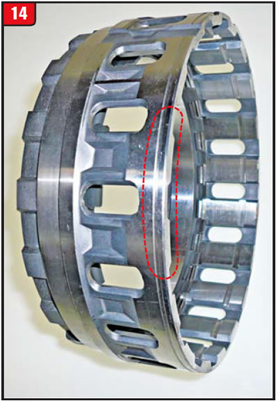
The next component that can contribute to the shifting problems is, in part, what distinguishes the 722.9 from the 722.6 transmission: the B3 brake. The B3 is the housing that is next in line behind the pump. The B3 brake is also model specific and can be identified by a thin groove around the outside diameter of the housing (Figure 14). As with the B1 brake, make sure that the stack-up and clearance are correct. Computer controls can compensate only so much to correct clutch-clearance issues.
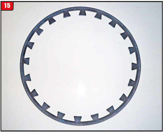
Another item of concern is the B1- and B3-brake piston return spring. The return spring is of the Belleville design and must be installed correctly, dish side up (Figure 15). As with any piston return spring, fatigue can occur and could lead to breakage. Always replace high-mileage or overheated Belleville springs to avoid problems.
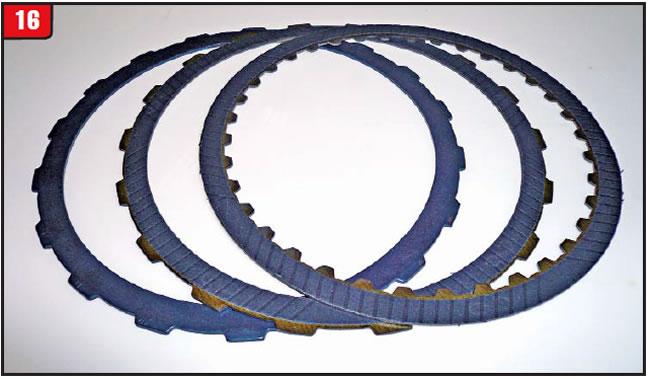
The frictions for the B1 and B3 brakes are the single-sided design and are the same for both brake positions. Quantities will vary between the B1 and B3 brakes and are model specific. As with any single-sided design, proper stack-up is critical. In addition to the friction plates is a cushion spring, which is installed first against the piston, followed by the external-tooth friction plate (Figure 16).
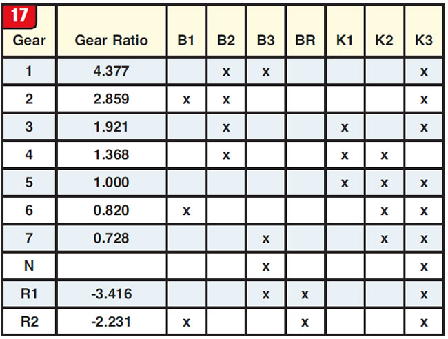
Refer to the chart in Figure 17 for the clutch-apply sequence. Notice that in addition to the 1-2 and 2-3 upshift pattern, which involves the B1 and B3 brakes, is the shift from sixth gear to seventh gear that also involves both components. Downshifts involving the B1 and B3 are as much of concern as upshifts.
In the end, the mechanical part of the transmission must be right, but then the controls, such as the ECM/TCM etc., must function correctly as well.

September 2013 Issue
Volume 30, No. 9
- Automatic transmissions in three-wheel vehicles
- DCT 02E: erratic engagements, no-start condition
- Mercedes 722.9: poor shift quality