
Issue Summary:
- 1997-2000 Ford F-150/F-250 pickups with 4R70W transmissions may have driveline vibration and rear-seal leaks.
- Cooler leaks on 2000-01 Ford Explorer/Mercury Mountaineer four-door vehicles with 5R55W transmissions may be caused by contaminants on the cooler tubes.
- On 2000 Cadillac Devilles, Eldorados and Sevilles and 2001 Oldsmobile Auroras with 4T80-E transaxles, slipping in fourth or no fourth gear with code P0734 may be caused by a warped lower-control valve-body channel plate.
- No movement or delayed engagement in a BMW with the ZF-5HP-18 may be caused by a shrunken bypass ball.
- We have furnished typical relay checks for Chrysler’s 41TE, 42LE and 42RE transmissions. Once the operation of a relay is understood, any relay can be checked with ease.
Vehicles Affected:
- 1997-2000 F-150, F-250 Light-Duty Trucks

A driveline vibration and/or a transmission-fluid leak from the rear seal in the extension housing may occur in some 4×2 vehicles with 139-inch wheelbases.

This may be caused by the extension-housing bushing or seal spinning or walking out because of excessive driveshaft flexing during extended high-speed operation.
Some vehicles will require alignment of the balance marks on the output shaft, driveshaft and universal-joint flange on the rear axle.

Check extension-housing bushing and seal. If the bushing or seal has spun out, repair or replace the extension housing and gasket. You may have to install a revised driveshaft that is 127mm (5 inches) in diameter.
Note:
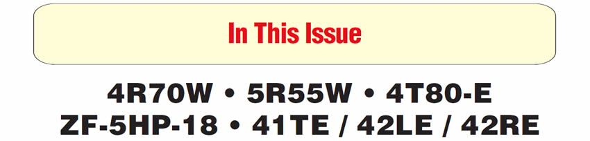
On vehicles built after 4/1/1998, the index paint marks on the output shaft, driveshaft and rear-axle flange must be aligned (Figure 1).
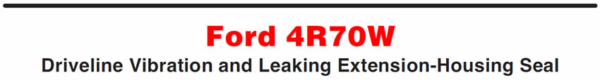
The index mark on the new output-shaft yoke must be in alignment with the index marks on the rear driveshaft tube and the universal-joint flange on the rear axle (Figure 2).

Part Number Part Name
- 1L3Z-4602-BB ……………………..Driveshaft (5.4L, 4X2, 4R70W, 139-in. WB, 93⁄4-in. Axle)
- 1L3Z-4602-CA ………….……….Driveshaft (5.4L/4.6L, 4X2, 4R70W, 139 in. WB, 101⁄4 in. Axle)
- F85Z-4602-BB ……….………….Driveshaft (4.6L/4.2L, 4X2, 4R70W, 139 in. WB, 8.8 in. Axle)
- F3LY-7A039-A…………………..Transmission Extension Housing
- F6AZ-7086-A …………………..Gasket – Extension Housing


Vehicles Affected:
- Ford Explorer/Mercury Mountaineer four-door vehicles built 11/13/2000 through 4/2/2001.
Some 2002 Explorer/Mountaineer four-door vehicles built during this period and equipped with the 5R55W transmission may exhibit a fluid leak where the cooler line connects to the transmission case.
This may be caused by contaminants on the surface of the cooler tube between the tube nut and flare or on the tube-nut threads, or by improper installation torque.
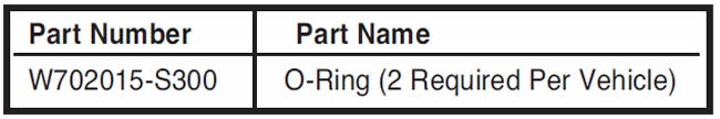
If fluid is leaking from the cooler lines at the transmission, you will need to disconnect and clean the cooler lines and tube nuts and install an O-ring in the case fitting:
- Remove cooler lines from transmission (Figure 3).
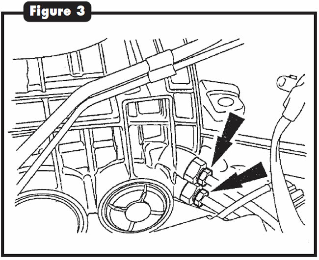
- Clean the threads on the cooler tube nuts, clean the cooler lines at the flare and clean the cooler-line surfaces between the line and the cooler tube nuts (Figure 4).
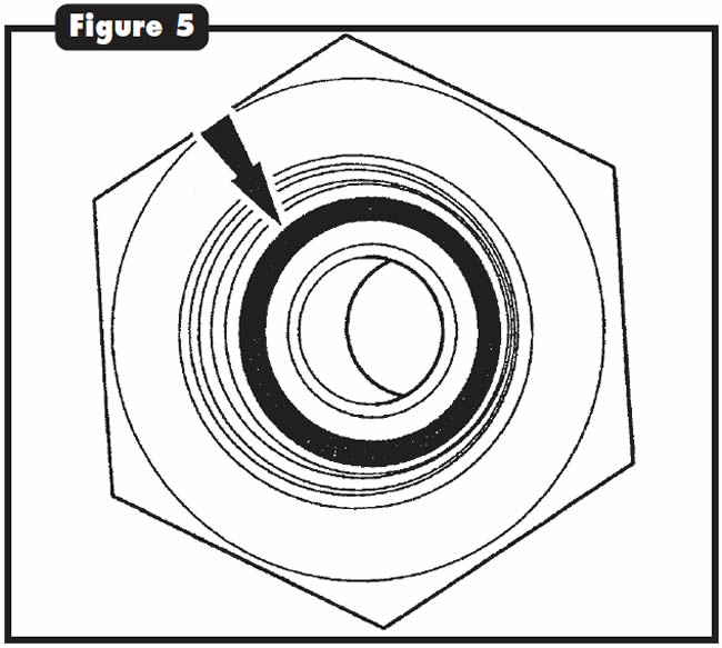
- Install the O-rings (W702015-S300) (See Figure 5).
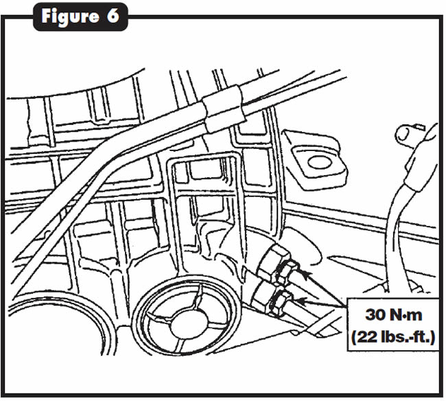
- Re-install the cooler lines into the case and tighten the cooler tube nuts to 30 N·m (22 lbs.-ft.)(See Figure 6).


Vehicles Affected:
- 2000 Cadillac Deville, Eldorado, Seville; 2001 Oldsmobile Aurora
Driver will complain of no 4th gear or slipping in 4th gear. The Service Engine Soon lamp may illuminate. Diagnostic trouble code P0734 may be set.
This condition may be caused by a warped channel plate (900 in Figure 7) in the lower control valve body, allowing the loss of fluid apply pressure to the 4th band.
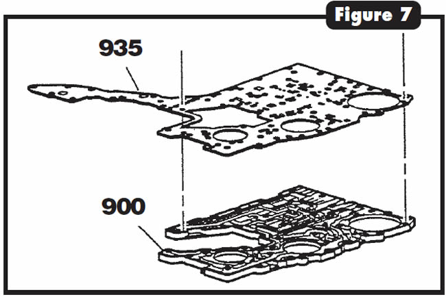
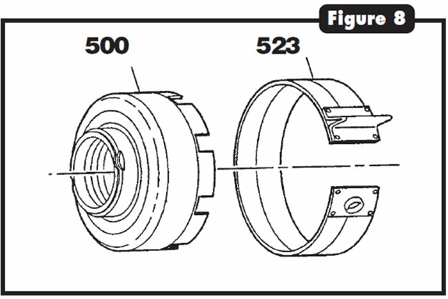
Using a scan tool, check and record DTCs that are set. Inspect the 4th band (523 in Figure 8) and the reverse-clutch housing (500) for wear. Replace them as necessary. Also replace the channel plate and the spacer-plate gasket (935 in Figure 7) in the lower control valve body.

Vehicles equipped with the ZF-5HP-18 may exhibit no movement or a delayed engagement before and/or after overhaul.
The cause may be that the bypass ball in the pump (See Figure 9) has shrunk and traveled back through the pump passage that leads to the torque-converter valve, causing the valve to stick in the stroked position (See Figure 10).
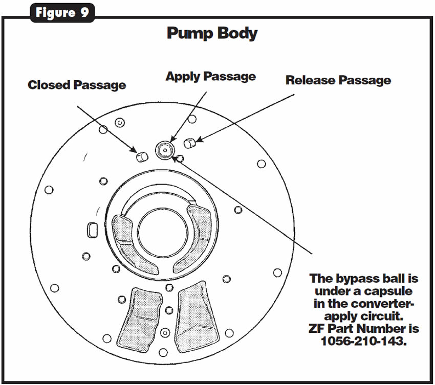
When the valve sticks in this position, it may cause fluid to drain from the torque converter after the vehicle has sat for a prolonged period. Then, when the vehicle is started, the torque converter may take 10 to 15 minutes to refill; this all depends on the positioning of the stuck torque-converter valve.
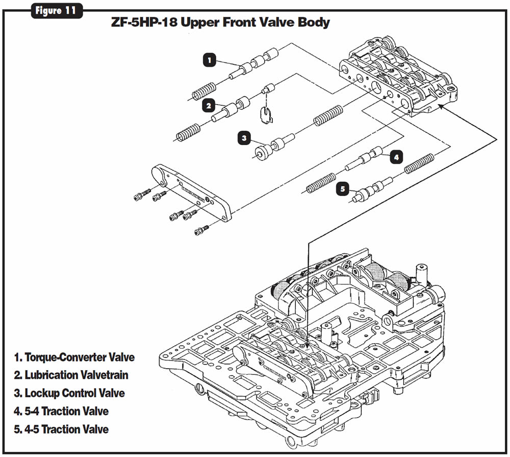
Locate the torque-converter valve (Refer to Figure 11) and free the valve, removing the shrunken bypass ball that was binding the valve’s movement.
Replace assembly in pump body with a new one from ZF, available under ZF part number 1056-210-143, if you can remove the capsule from the pump body (See Figure 9).

Diagnostic Tip:
Relays have become more widely used in the automotive industry during the past several years, particularly for controlling electrical circuits related to the transmission. Relays are normally open switches that close when energized. The purpose is to isolate one part of an electrical circuit from another. Once you understand the operation of a relay, you can check any relay with ease.
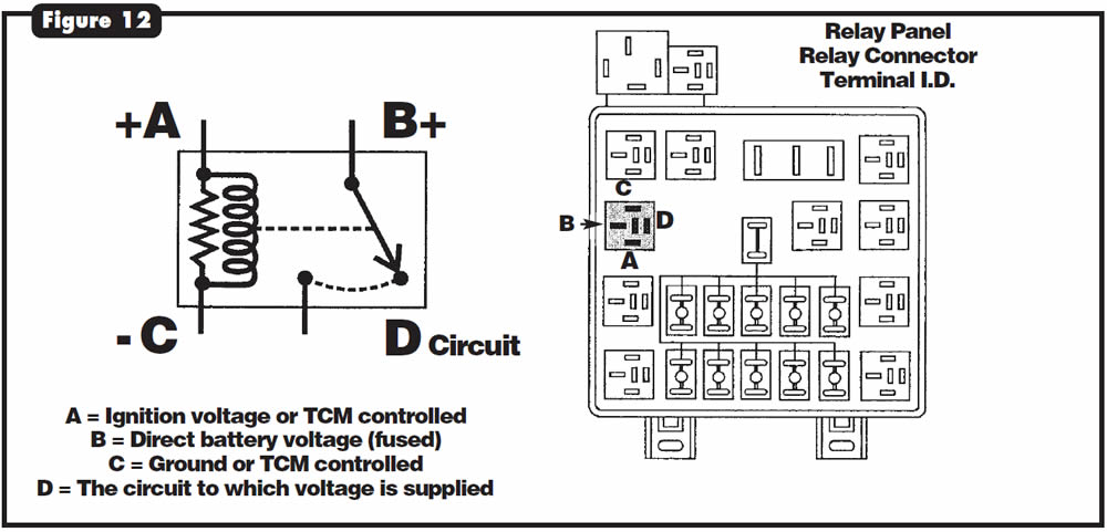
Figure 12 is a wiring diagram of a typical relay. Each terminal is lettered for identification. Terminal A energizes the relay from either the ignition or a control module. Terminal B is a fused direct battery-feed terminal. Terminal C is a ground circuit going to either a direct ground or a control module. Terminal D is the circuit that the direct battery-feed terminal (terminal B) will supply when the switch is closed. When terminal C is grounded and voltage is supplied to terminal A, the relay becomes energized, pulling two contacts together and joining terminals B and D.
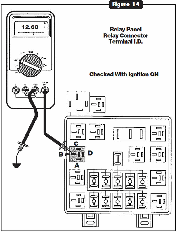
To check a relay for proper operation, supply 12 volts to terminal A, ground terminal C, and check for continuity across terminals B and D with a DVOM. If terminal identification is uncertain, simply unplug the relay from the connector. Place the negative lead of a DVOM to ground with the meter set to DC volts. With the positive lead, carefully check each terminal in the connector with the ignition off (See Figure 13).
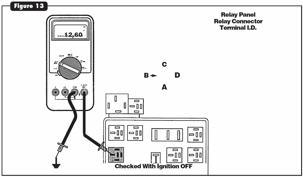
The terminal in the connector that provides battery voltage will be terminal B. The terminal opposite of terminal B is D (See Figure 12). Now turn the ignition on. Recheck the remaining two unidentified terminals. The one that has voltage with the ignition on is terminal A (See Figure 14). The remaining terminal is the ground terminal, C.
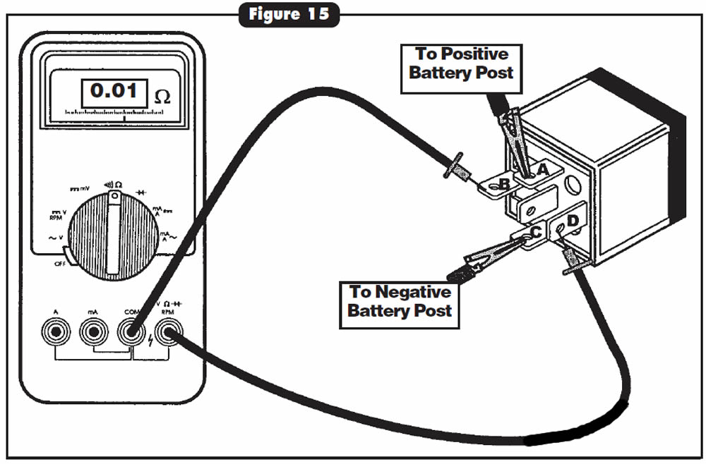
With the terminals identified in the connector, the relay terminals can be identified and ready for testing. Run two jumper wires from the battery. Place the jumper from the positive battery post to terminal A. Have the jumper lead from the negative battery post prepared to ground terminal C. With a DVOM set to ohms, place leads across terminals B and D. When you ground terminal C, you should hear a click and see continuity on the meter display (See Figure 15). When terminal C is not grounded, the switch should be open and the meter should display the same. If the relay does not open and close as described, replace the relay.

October 2001 Issue
Volume 18, No. 10
- Ford 4R70W: Driveline Vibration and Leaking Extension-Housing Seal
- Ford 5R55W: Leak From Transmission Cooler Lines at Case Connector
- 4T80-E: Slipping in Fourth or No Fourth Gear
- BMW ZF-5HP-18: No Movement or Delayed Engagement
- Chrysler 41TE, 42LE & 42RE Transmissions: Typical Relay Checks