
Issue Summary:
- No forward engagement in a Ford E4OD may occur because the plastic-caged low roller clutch was installed incorrectly.
- An A4LD in Ford light trucks may require shift-lever PRNDL adjustment because the cable-assembly locking tab is not fully seated.
- If you have a Chrysler A-604 with a broken tapered snap ring in the underdrive/overdrive reaction plate, be sure you install the late-type snap ring.
- We have corrections for bind-up or 2nd-gear starts on KM-177, and a pump-gear change on KM 175.
- In Ford Probe 4EAT and Mazda G4A-EL units, a
4-2-3-1 shift pattern after rebuild may be caused by reversed shift solenoids. - We also have the procedure for FIPL (fuel-injection pump lever) sensor adjustments on the Ford E4OD.


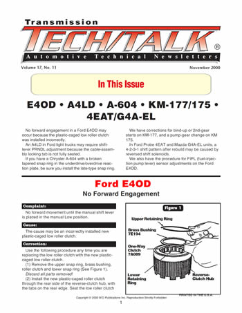
No forward movement until the manual shift lever is placed in the manual Low position.

The cause may be an incorrectly installed new plastic-caged low roller clutch.

Use the following procedure any time you are replacing the low roller clutch with the new plastic-caged low roller clutch.
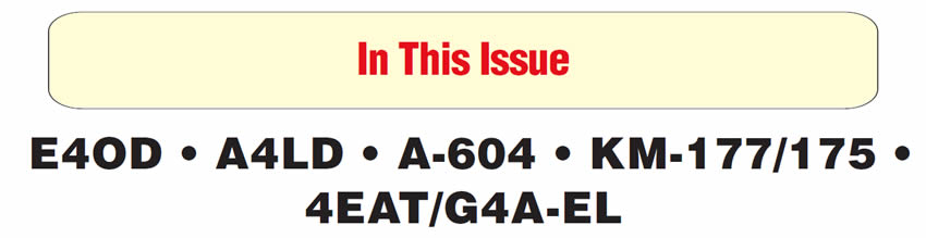
- (1) Remove the upper snap ring, brass bushing, roller clutch and lower snap ring (See Figure 1). Discard all parts removed!
- (2) Install the new plastic-caged roller clutch through the rear side of the reverse-clutch hub, with the tabs on the rear edge. Seat the low roller clutch into the reverse-clutch hub, and rotate clockwise to seat rollers and lock tabs in place.
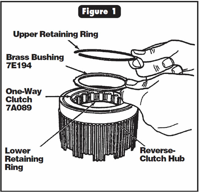
See Figure 2 for proper installation.

- Plastic-Caged Low Roller Clutch ……………………….F3TZ-7A089-A


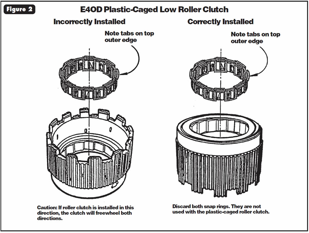
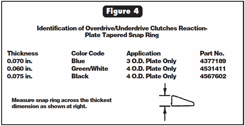
The color-coded tapered snap ring that goes on top of the underdrive/overdrive reaction plate in the input housing is found broken, usually in many pieces (See Figure 3).
Snap ring is not thick enough.
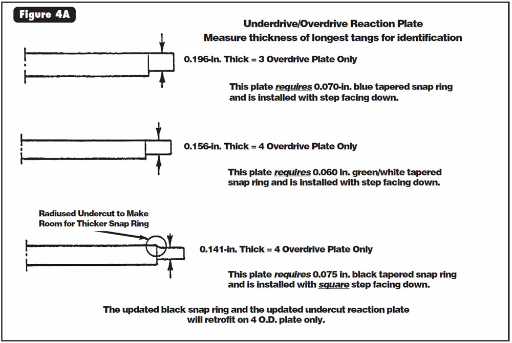
Install updated (thicker) tapered snap ring, and the updated underdrive/overdrive reaction plate. These two pieces must be installed together. Neither part is compatible with the previous parts. These parts will retrofit vehicles with the 4 overdrive pack only.
- Updated Tapered Snap Ring (Black 0.075-in. Thick) ………..4567602
- Underdrive/Overdrive Reaction Plate (Updated Selective):
- 0.215 in.-0.219 in. Thickness…………………..4567643
- 0.234 in.-0.238 in. Thickness…………………..4567642
- 0.253 in.-0.257 in. Thickness…………………..4567641
- 0.273 in.-0.277 in. Thickness…………………..4567640
Note:
This change was implemented at start of production for all 1993-model A-604 transaxles. For identification of the individual parts you may have on your shelf, see Figure 4.

Some 1989-93 Ford Ranger, Explorer, Aerostar, Econoline and Bronco models may not show the correct position of the shift lever on the PRNDL.
The cause may be that the locking tab for the transmission control cable is not fully seated or secure in the cable body.
If the shift-lever position on the PRNDL does not correspond to the actual shift position, check the locking tab on the control cable to be sure that it is fully seated (See Figure 5).
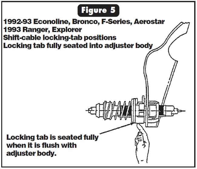
If the locking tab is not fully seated flush with the cable-adjuster body, follow this procedure:
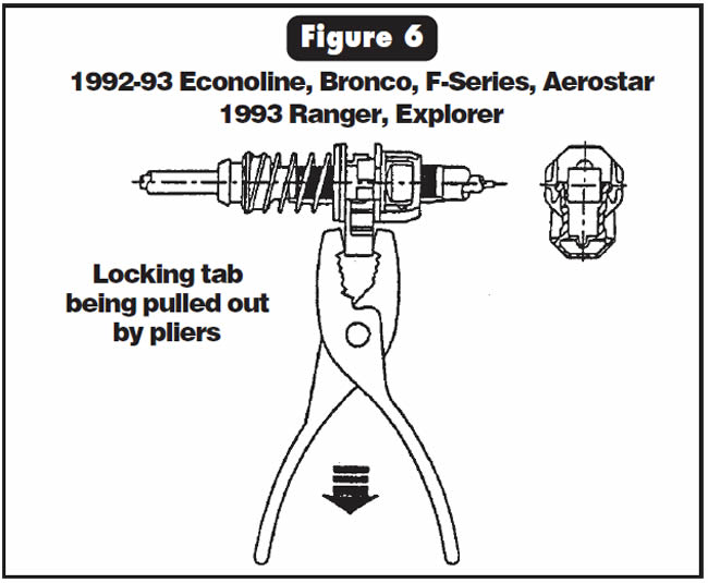
- 1) Hold the cable in the bracket with one hand while removing the tab from the adjuster body with a pair of pliers in the other hand (See Figure 6). You will need to apply about 20 pounds of force to remove the locking tab.
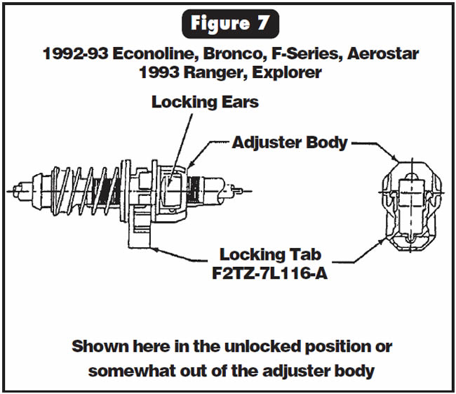
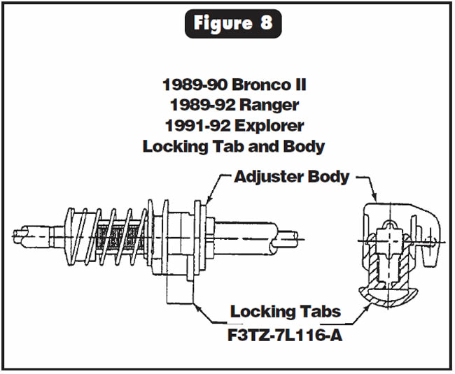
- 2) Replace the existing locking tab with F2TZ-7L116-A for 1993 Ranger and Explorer, and F3TZ-7L116-A for 1989 Ranger, 1991-92 Explorer and 1989-90 Bronco II.
- 3) Push the new locking tab into the adjuster only halfway (See Figures 7-8).
- 4) Adjust the shift system according to the Ford service manual before fully seating the new locking tab.


A bind-up on a 2-3 shift and/or 2nd-gear starts, or a bind-up in reverse, after overhaul.
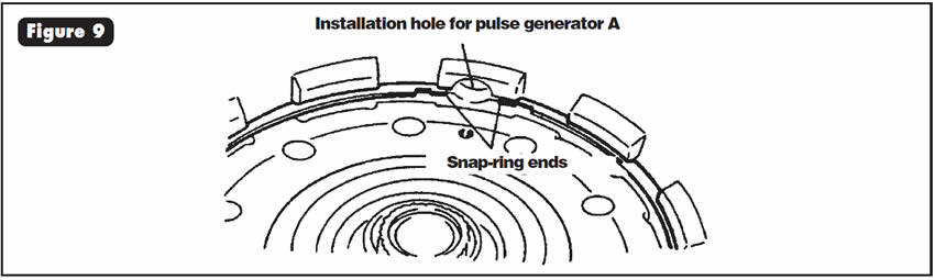
The snap ring that holds the center support into the case may have been mispositioned, and when pulse generator A was installed, one end of the snap ring came out of its groove and jammed against the sun shell.
Install the snap ring so that its open end faces the entrance hole in the case for pulse generator A (See Figure 9).


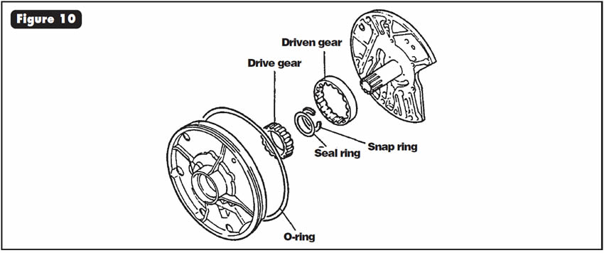
Some KM 175 transaxles had a change made to the drive gear. The previous drive gear has a groove machined on the inside diameter to accommodate an O-ring that sealed against the converter neck. The drive gear now has an oil seal that is retained by a snap ring. Figure 10 shows the correct assembly procedure with the snap ring facing the pump cover. The part number for the oil seal is MD729928.

After you have finished the rebuild and installed the transaxle, the vehicle starts in 4th gear, then shifts into 2nd gear, followed by shifts to 3rd gear and then to 1st gear. The last shift sometimes is described as a shift into neutral because of vehicle speed at the time of the shift.
The vehicle also will display a 1-2-Neutral shift when the driver goes through the shift pattern manually, and a slipping condition on heavy acceleration.
The cause may be that the 1-2 and 2-3 shift solenoids are reversed in their locations in the valve body (See Figure 11).
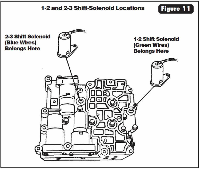
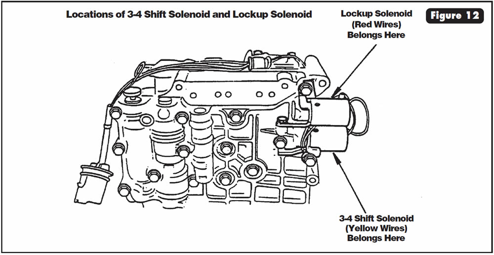
Install the shift solenoids in their proper locations, as shown in Figures 11 and 12. Use Figure 11 for the 1-2 and 2-3 shift solenoids, and Figure 12 for the 3-4 and lockup solenoids.

Use the following procedure to adjust and/or verify the adjustment of the FIPL (fuel-injection pump-lever) sensor on Ford trucks equipped with the 7.3L diesel engine and E4OD transmission.
- (1) Verify that you have the latest-design FIPL sensor installed on the vehicle, OEM part number F2TZ-9B989-C. If not, stop and install one NOW.
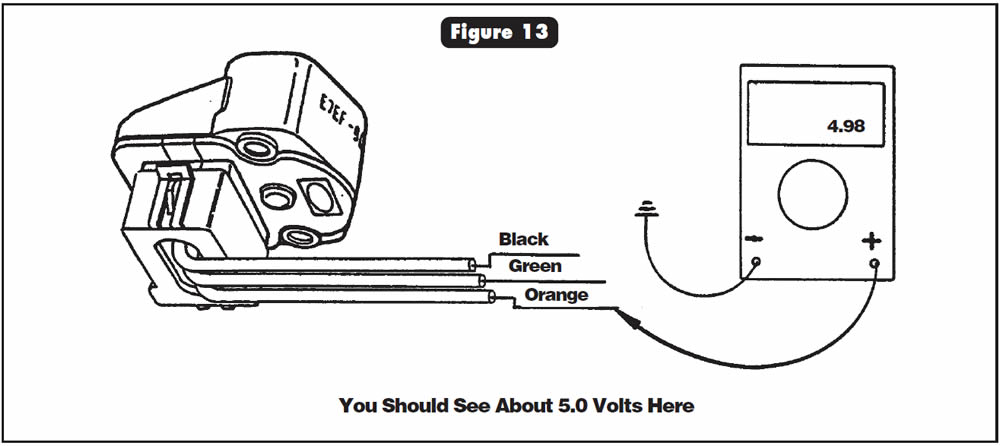
- (2) With your volt/ohmmeter set to DC volts and the key in the ON position, back-probe the orange wire from the FIPL sensor with the red lead from your volt/ohmmeter, and the black lead from your volt/ohmmeter to a good ground (See Figure 13). You should see about 5.0 volts here (See Figure 13).
- (3) With your volt/ohmmeter set to DC volts and the key in the ON position, back-probe the green wire from the FIPL sensor with the red lead from your volt/ohmmeter, and back-probe the black wire from the FIPL sensor with the black lead from your volt/ohmmeter, as shown in Figure 14.
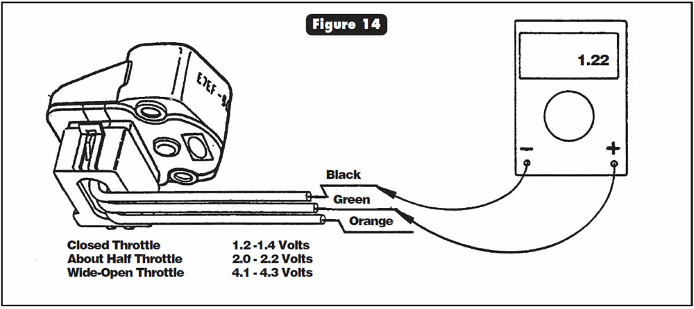
You should see the following voltages:
- Closed Throttle 1.2-1.4 Volts
- About Half Throttle 2.0-2.2 Volts
- Wide-Open Throttle 4.1-4.3 Volts
Note:
If wide-open-throttle voltage gets above 4.5, the PCM will set a trouble code for TPS voltage high.
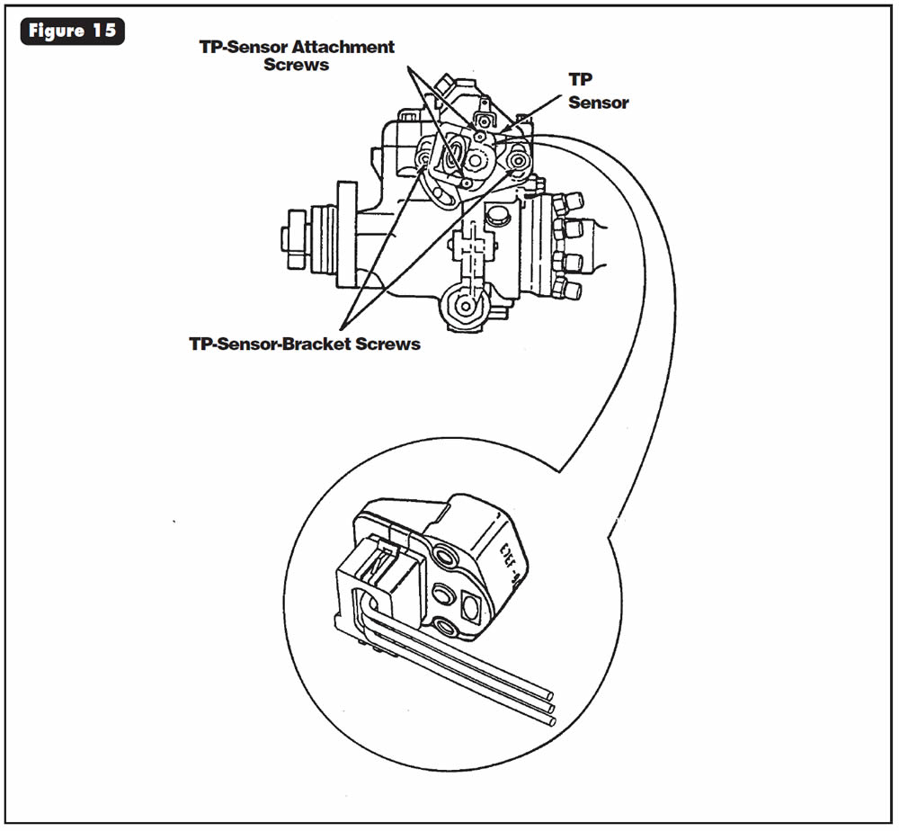
- If the voltage is not within the preceding specifications, loosen the two screws that attach the FIPL sensor to the mounting bracket (See Figure 15) and rotate the sensor until you achieve those readings.
- If voltage readings for the FIPL sensor still do not fall within the specifications listed, you can attempt adjustment by loosening the attaching bolts for the FIPL-sensor bracket (See Figure 15) and rotating the bracket.
Note:
Movement of the bracket normally is not used as a means for adjustment. If required, remove the epoxy from the attaching bolts for the bracket and rotate the bracket until you achieve the correct readings.
- Service Information: FIPL Sensor, 7.3L Diesel (New Design)……….. F2TZ-9B989-C

November 2000 Issue
Volume 17, No. 11
- Ford E4OD: No Forward Engagement
- Chrysler A604: Underdrive/Overdrive Reaction-Plate Tapered Snap Ring Breaking
- Light-Truck A4LD: Shift-Lever PRNDL Adjustment
- KM 177: Bind-Up or 2nd-Gear Starts
- KM 175: Pump Gear Change
- Ford Probe 4EAT and Mazda G4A-EL: Displays 4-2-3-1 Shift Pattern After Rebuild
- Ford E4OD: Adjustment of FIPL Sensor