No forced throttle downshifts

No forced throttle downshifts

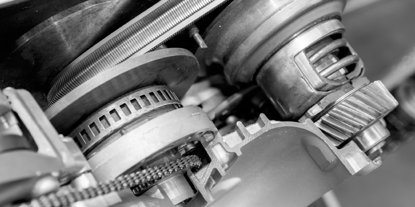
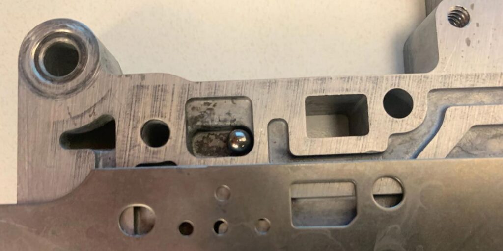
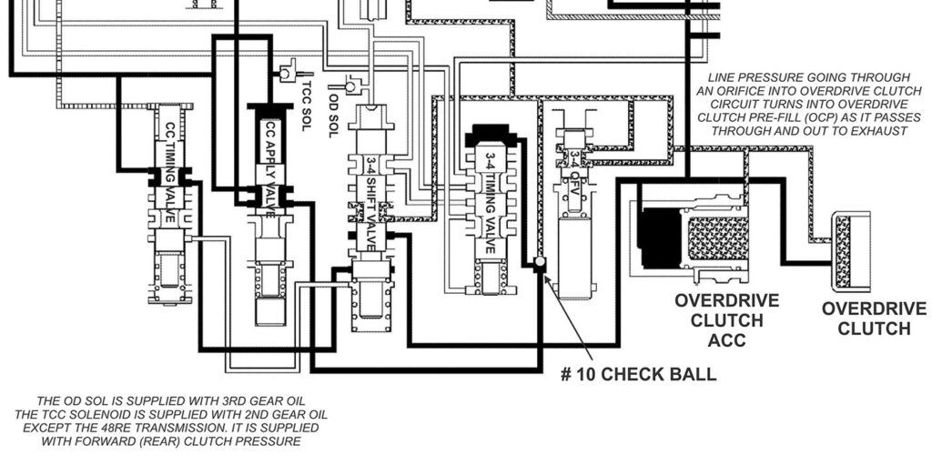
Twenty-five years ago, Chrysler introduced a 0.187-in. (4.77mm) steel, #10 check ball (figure 1, above) in the 42RE valve body which continued to be used throughout the entire RE series of transmissions (42, 44, 46, 47 and 48RE) as they were launched.

This small check ball is quite active, having several functions during the course of one complete drive cycle. The #10 check ball was implemented to ensure smooth sequential downshifts. These are its three basic functions:

Function #1: When the converter clutch is off, it sends Overdrive Clutch Prefill (OCP) pressure (0-5 PSI) to the 3-4 Timing Valve while simultaneously blocking it from entering the converter clutch apply circuit (as seen in figure 2).

Shift-Pointers-March-Figure-2-1400Figure-2-1400
Figure 2.

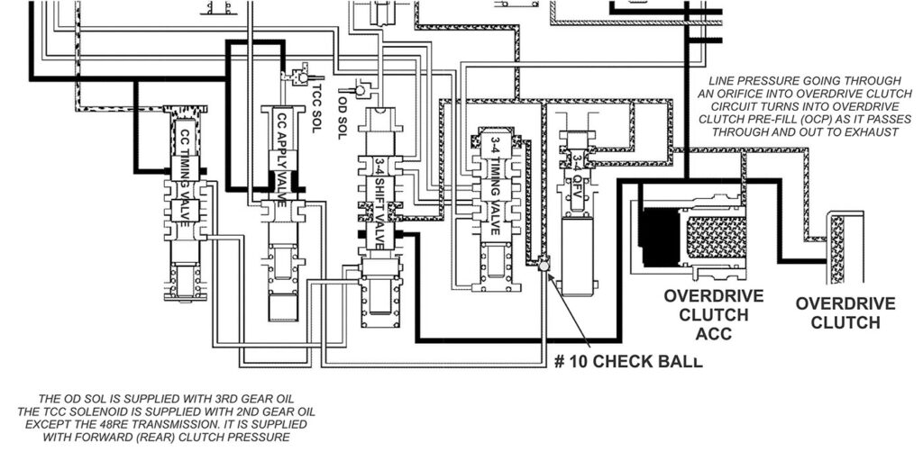
Function #2: When the converter clutch is commanded on before fourth gear, this ball will then block OCP pressure to the 3-4 Timing Valve, allowing pressure from the converter clutch apply valve to stroke the 3-4 Timing Valve (as seen in figure 3).  

Shift-Pointers-March-Figure-3-1400
Figure 3.

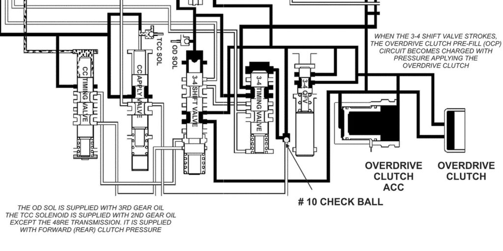
Function #3: When a shift into fourth gear takes place, Lock-up turns off and the Overdrive Solenoid turns on stroking the 3-4 Shift Valve. Once the 3-4 Shift Valve strokes, it fills the OCP circuit with pressure, applying the Overdrive Clutch. This same pressure is routed to the 3-4 Quick Valve, the Accumulator and the # 10 check ball where it is then sent to stroke the 3-4 Timing Valve (as seen in figure 4).

Shift-Pointers-March-Figure-4-1400
Figure 4.

There is an additional hydraulic function that took place when this ball was added. It occurs when the converter clutch is commanded on in fourth gear. When the computer turns the lock-up solenoid on, it strokes the converter clutch apply valve. This charges a circuit that causes the converter clutch timing valve to stroke. The converter clutch timing valve then sends line pressure to the rear spool of the 3-4 shift valve (as seen in figure 5).

Shift-Pointers-March-Figure-5-1400
Figure 5.

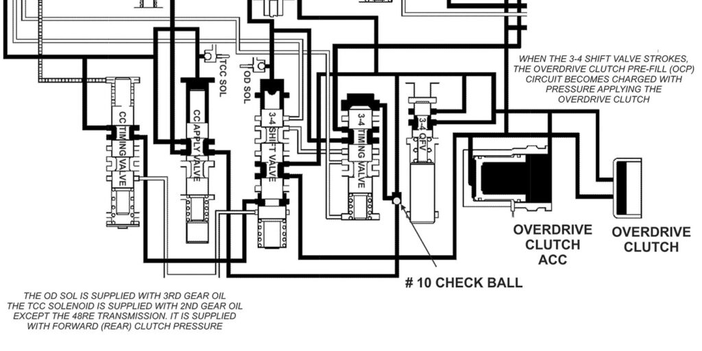
This is added insurance to keep the shift valve stroked. And again, all this is done to assist in providing a smooth sequential release of the converter clutch, followed by a downshift. It prevents the converter clutch from releasing on top of a downshift which would be felt as a harsh downshift.

Let’s now talk about one of the failures that can be experienced with this hydraulic system. The complaint that typically accompanies this failure is when there are no forced throttle downshifts when the transmission is hot. This complaint only occurs once the transmission has shifted into overdrive followed by the converter clutch being commanded on. The scan tool data reveals that at wide open throttle the lock up solenoid and the overdrive solenoid are being command off, yet the transmission remains in overdrive with the TCC applied. If you pull the shift lever from the “drive to the number 2 position” it will downshift to 2nd gear. A careful road test may also reveal that once the transmission is hot, the lock up clutch may engage after the 1-2 up shift.

The cause is that the lock up solenoid has mechanically failed, preventing it from exhausting when it has been commanded off by the computer (as seen in figure 6).

Shift-Pointers-March-Figure-6-1400
Figure 6.

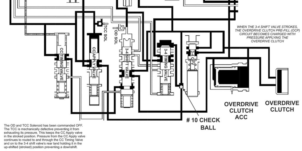
This keeps both the converter clutch apply valve and 3-4 shift valve stroked in the upshifted position. The converter clutch switch valve is also kept stroked, keeping the converter clutch applied. By installing a new TCC/OD solenoid assembly, these malfunctions are resolved.

You May Also Like

Sometimes, a diagnostic code is all you need

With ATSG having the opportunity to help shops solve problems, sometimes we get faced with some real doozies. A shop will call and give us a laundry list of DTCs, leaving us to think someone must have a bulkhead connector unplugged. We then go through the arduous task of deciding which codes prompted other codes

With ATSG having the opportunity to help shops solve problems, sometimes we get faced with some real doozies. A shop will call and give us a laundry list of DTCs, leaving us to think someone must have a bulkhead connector unplugged. We then go through the arduous task of deciding which codes prompted other codes to set—we’re actually diagnosing diagnostic codes themselves at that point. So, when an issue comes up on our help line with codes that actually tell the story, it makes for a nice change, as well as a quick pathway to a repaired vehicle.

10L80 and 10R80 pump gear differences

You may have seen an article in the August 2023 issue of Transmission Digest called “GM 10L80: A new kind of pump noise,” which goes over how the front cover housing in the 10L80 is fitted with a converter drive gear and idler gear. The idler gear drives the pump’s driven gear, and is press

Shift Pointers: What to do when the 62TE TRS tab breaks

How frustrating it is when on a hot summer day, as you go to open a nice cold can of your drink of choice, and the tab breaks off? You are outside, away from any tools to remedy the problem quickly. It now requires a MacGyver mentality looking around at the resources available to get

Going the extra mile: Proving your transmission repair suspicions

A 2003 Honda Pilot with a five-speed three-shaft transmission came into our shop with a customer concern that the vehicle had no power, and the “D” light was flashing. I first did a scan for codes to see what it came up with, and the scan tool returned four DTCs: P1298 (ELD voltage high), P0135 (H02S

RRfeature-1400
Diagnosing Ford 10R60, 10R80 and 10R140 series speed sensor issues

Ford 10-speed 10R series transmissions utilize four two-wire, Hall-effect sensors — TSS, ISSA, ISSB and OSS — for providing speed signals to PCM or TCM. They are supplied nine volts by a PCM or TCM and assist in the control of clutch apply/release timing that is used in determining shift quality, including TCC. Related Articles

Other Posts

Shift Pointers: Failures caused by incorrect tire sizes

For years ATSG has produced a wide range of issues related to improper tire sizes on vehicles. Even under-inflated tires have been known to cause issues. Problems such as premature failure with an active 4WD transfer case will occur with incorrect tire sizes. Related Articles – Valve body and component suppliers: A comprehensive list –

Shift-Pointers-Jan-Figure-1-1400
Understanding lube flow control valves in Toyota/Lexus UA/UB80 transmissions

The Toyota/Lexus UA80 and UB80 transmissions first came out in 2017 in Highlanders and Siennas. The UA80 is used in V6 applications, and the UB80 is paired with four-cylinder versions. They have been called Toyota New Global Architecture type transmissions, and alternately referred to as the “Direct Shift 8AT” eight-speed automatic transmission. This transmission was

Tasc-Tip-December-Figure-1---LFC-Valve-OE-Partial-Circuit-Diagram-1400
How reading through service bulletins can turn a technician into the customer’s hero

Over the last 28 years of being a technician, I have developed the habit of checking for and reading technical service bulletins at the forefront of the diagnostic process, especially when an unfamiliar vehicle exhibiting blatant or straightforward concerns comes into the shop. I have found many valuable nuggets of information while reading over these

Sometimes, you should sweat the small stuff

It’s a common phrase: There may have been a time when you worried about something, and someone who knew what you are going through said, “Hey, don’t sweat the small stuff.” Sometimes, this may be good advice. But other times, it may be wise to handle the small stuff before it becomes bigger “stuff.”  Related