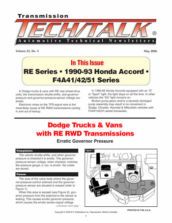


Issue Summary:
- In Dodge trucks & vans with RE rear-wheel-drive units, the transmission shuttle-shifts, and governor pressure and governor-pressure-sensor voltage are erratic.
- Electronic noise on the TPS-signal wire is the most-likely cause of RE RWD transmissions cycling in and out of lockup.
- In 1990-93 Honda Accords equipped with an “S” or “Sport” light, the light stays on all the time. In other vehicles the “D4” light remains on.
- Broken pump gears and/or a severely damaged pump assembly may result in no movement in Dodge, Chrysler, Hyundai & Mitsubishi vehicles with F4A41/42/51-series transaxles.


The vehicle shuttle-shifts, and when governor pressure is checked it is erratic. The governor-pressure-sensor voltage, when checked, matches the pressure gauge; it, too, is erratic. No codes are stored.

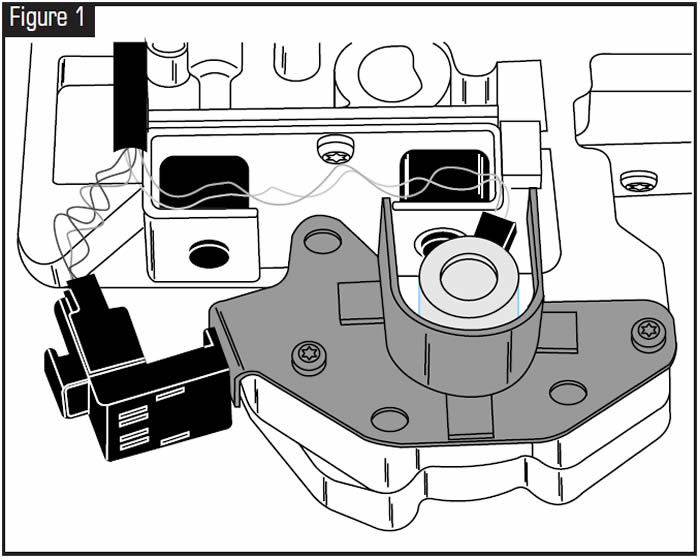
The area of the valve body where the governor-pressure-control solenoid and the governor-pressure sensor are situated is warped (refer to Figure 1).
When this area is warped (see Figure 2), governor pressure from the solenoid to the sensor is leaking. This causes erratic governor pressure, which causes the erratic sensor-signal voltage. This causes oil at the tip of the sensor to vary, which causes the sensor to vary the signal voltage. The PCM will react by varying the solenoid operation, which will result in erratic governor pressure.
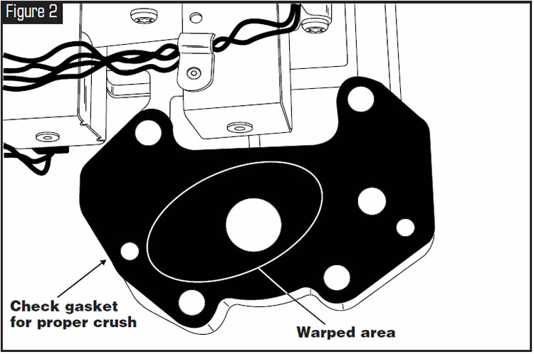

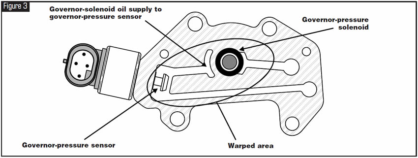
Check the crush on the solenoid/sensor gasket, which might reveal warpage in this area. Flat-sand the solenoid/sensor mounting block as well as that area of the transfer-plate section of the valve body (refer to Figure 3).


Vehicles with the RE RWD transmissions cycling in and out of lockup.
Possibly noise on the TPS-signal wire.
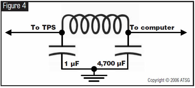
There are many causes for electrical noise. We most strongly recommend that you repair the source of the noise rather than filtering the noise. First clean the ground cable where it attaches to the block. Many times the ground cable is attached to a painted block. When the source of the noise is elusive, or repairing the source of the noise is expensive, you can filter the noise out of the signal using an L-C type of “pi” filter on the TPS-signal line. These filters are readily available at any car-stereo installation shop, and many retail electronics outlets (Echlin RD-13 or equivalent). It is fairly simple to assemble your own as well.
To build an L-C “pi” filter you will need the following:
- 0.68-µH (microhenry) choke coil (Jameco 372103 or equivalent)
- 1-µF (microfarad) capacitor (Jameco 10867PS or equivalent)
- 4,700-µF capacitor (Jameco 93673PS or equivalent)
- A box to mount it in (Jameco 18913 or equivalent)
- 1 crimp-on ground ring (Jameco 302762 or equivalent)
- 2 butt connectors (Jameco 320562 or equivalent)
- Wire (12-inch blue, 12-inch black, 12-inch violet)
- Solder
- (Optional) enough epoxy to fill the box. (A complete assembled unit is available from ATSG.
You can obtain Jameco parts at http://jameco.com, or your local professional electronic-parts store.)
Solder the parts together as shown in the schematic in Figure 4 and the illustration in Figure 5.
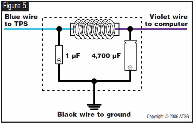
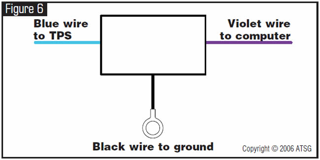
Install the filter by cutting the TPS-signal wire and feeding that signal through the blue wire in the filter (the 1-µF side to the TPS and the 4,700-µF side to the computer), then ground the black ground wire to a good ground (the better the ground, the cleaner the signal) as shown in Figure 6.

In vehicles equipped with an “S” or “Sport” light, that light stays on all the time. In other vehicles the “D4” light remains on all the time. Codes cannot be retrieved. Vehicle is stuck in third gear except when shifter is in manual 2 or manual 1 position; then, vehicle is in second gear.
One cause of this problem is a bad computer. A specific logic circuit has fried because of other problems in the power-supply section of the computer.
Repair the affected areas of the computer, or replace the computer.
The repair for this particular problem is fairly easy to do. No proprietary parts are required, so you can find all of them at your local electronics store. The repair requires only moderate soldering and board-repair skills. There are five parts to replace, one jumper and one bridge to install, and two trace cuts to make.
Parts:
- 1 220-µF 10-WVDC capacitor
- 1 330-µF 35-WVDC Capacitor
- 1 33-µF 10-WVDC capacitor
- 2 15-ohm 0.5-watt resistors
- 1 6-inch #24 jumper wire Solder
Tools:
- Soldering iron
- Razor knife or dental tool
- Screwdriver, Phillips
- Needle-nose pliers
- Wire cutters
Optional:
- Desoldering tool or iron
- Small rotary tool
Procedure:
- Step 1: Remove and replace C32 with 330-µF capacitor (see Figure 7).
- Step 2: Remove and replace C33 with 33-µF capacitor (see Figure 7).
- Step 3: Remove and replace C28 with 220-µF capacitor (see figure 7).
- Step 4: Remove and replace R41 and R42 with 15-ohm 0.5-watt resistors (see Figure 7).
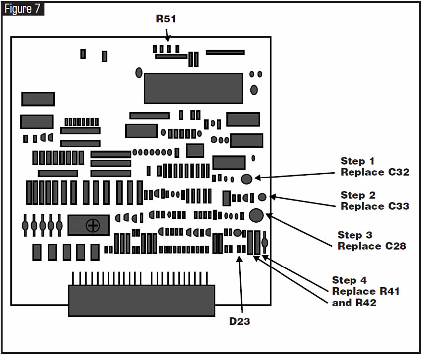
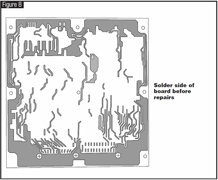
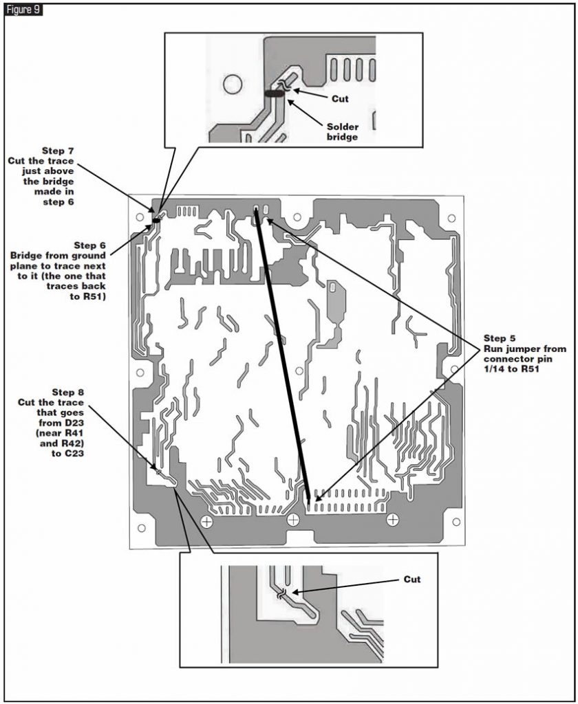
- Step 5: Solder a jumper wire from the trace where pins 1 and 14 of the main connector are, and the small pad in the middle of the ground plane where R51 is connected (see figures 8 and 9).
- Step 6: Make a solder bridge between the ground plane and the next trace in (which goes to the top of the board, then to R51) (see figures 8 and 9).
- Step 7: Make a cut in the trace above the bridge just made (see figures 8 and 9).
- Step 8: Make a cut in the trace that starts at D23 (see figures 8 and 9).

Vehicles equipped with the F4A41/42/51-series transaxle may exhibit a no-move condition. The fluid level may read high, and fluid condition is described as good.
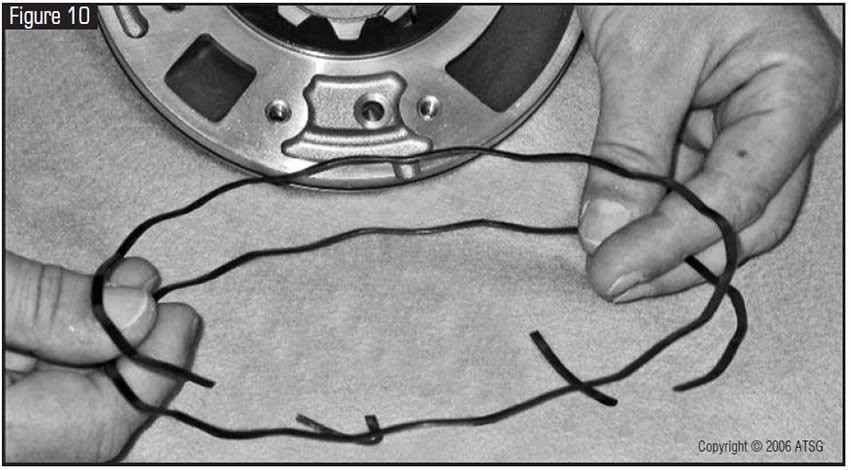
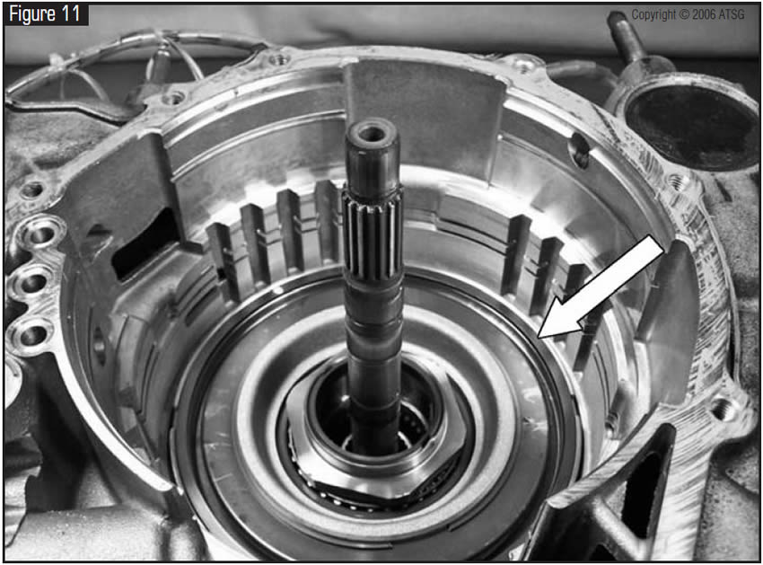
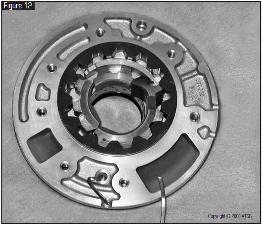
The cause may be broken pump gears and/or a severely damaged pump assembly. You may find pieces of the low/reverse spiral cushion wave spring (see Figure 10) that goes on top of the low/reverse-clutch assembly (see Figure 11) lodged between the pump gears (see Figure 12).
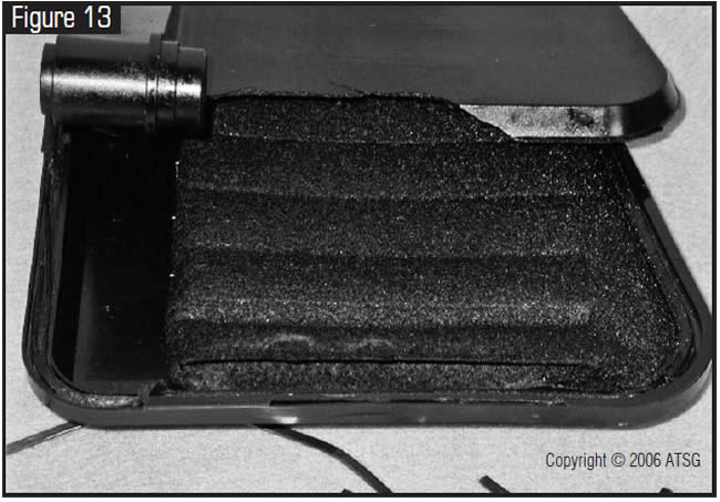
When the filter is cut open, there is a 3- to 4-inch section of filter media that is not crimped along the edge of filter halves during assembly. This allows the broken wave spring to enter the pump assembly (see Figure 13).
Replace pump and filter. Some aftermarket filters have been found to have no problems with the filter-media assembly. Update the low/reverse spiral cushion wave spring to a one-piece circular wave spring.
Note:
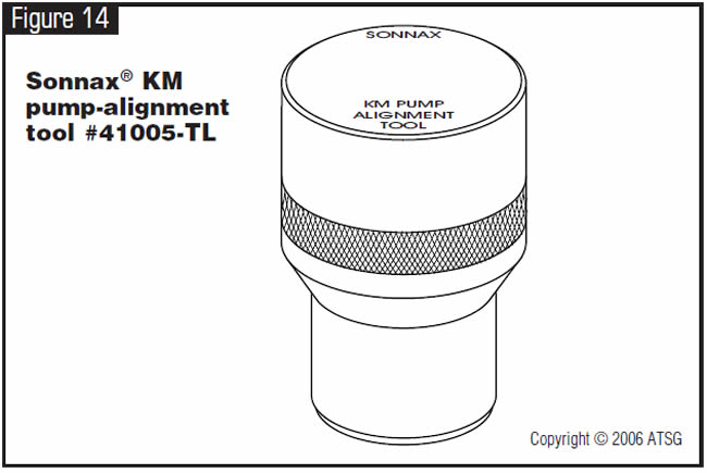
One other issue that plagues this transmission is front-seal leakage and/or a damaged pump bushing after rebuild, within as little as a few minutes during road test or in a couple of days. The original pump assembly is aligned during manufacturing, and there are no leading edges or alignment pins to align the pump. An alignment tool is available from Sonnax, part number #41005-TL (see Figure 14).
With the alignment tool in place as shown in Figure 15, torque the pump bolts to 80-85 lb.-in.
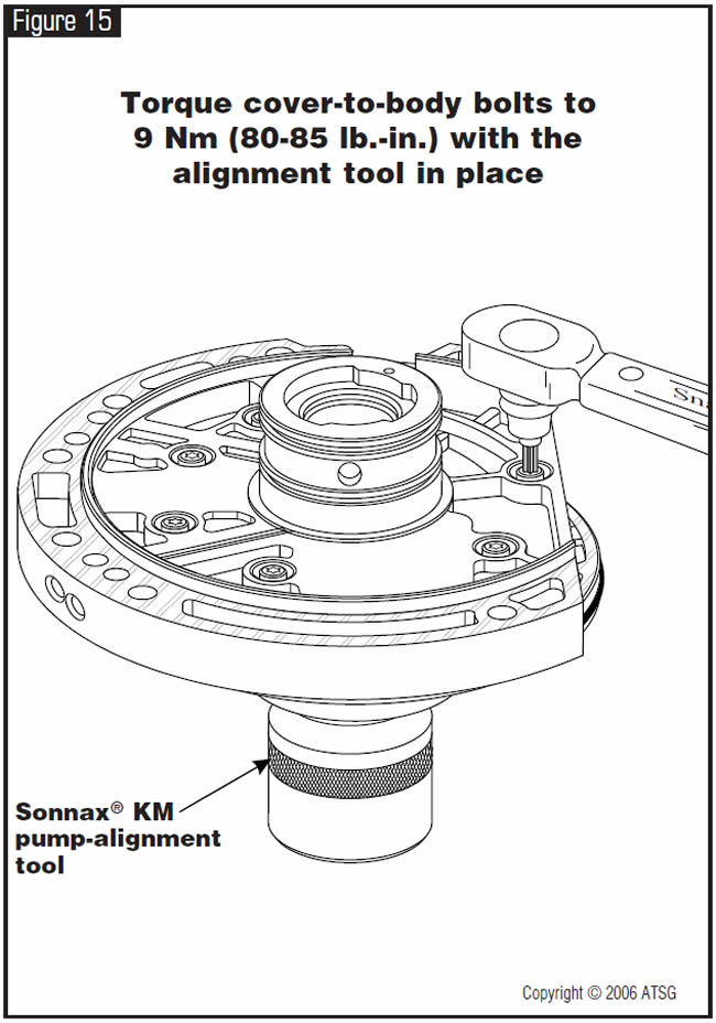
Do not try to align the pump with the torque converter. This procedure, when attempted, has had disastrous results.
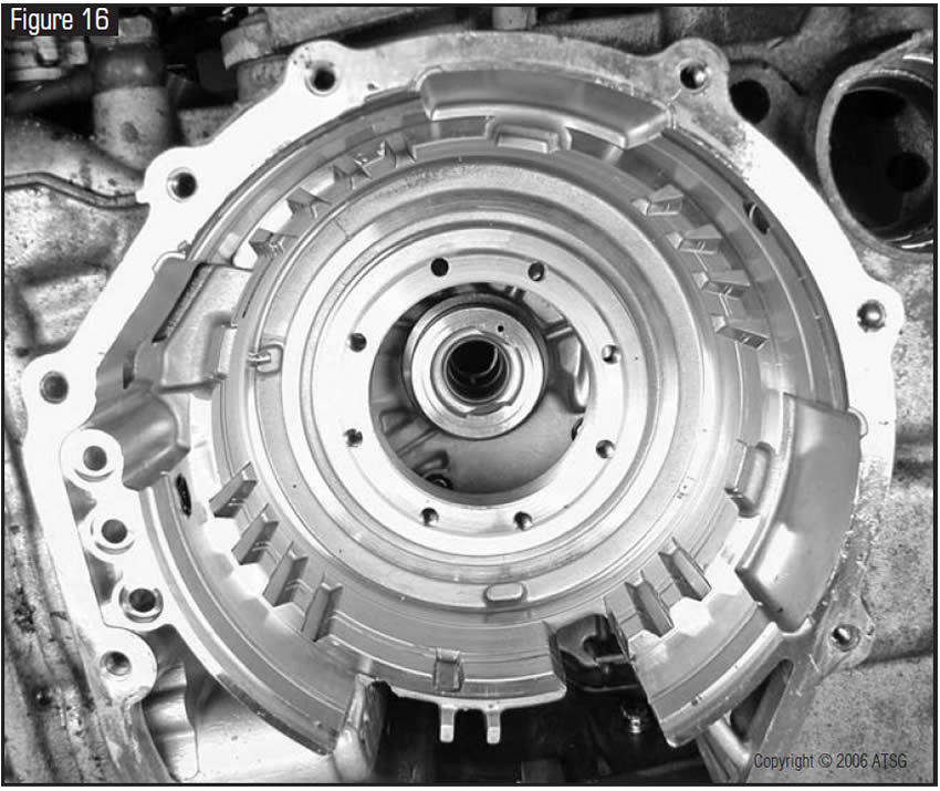
The only alternative method of aligning the pump without the tool is to assemble the pump body and cover with the bolts finger tight. Place the pump in the rear case half with the transfer gear removed (see Figure 16).
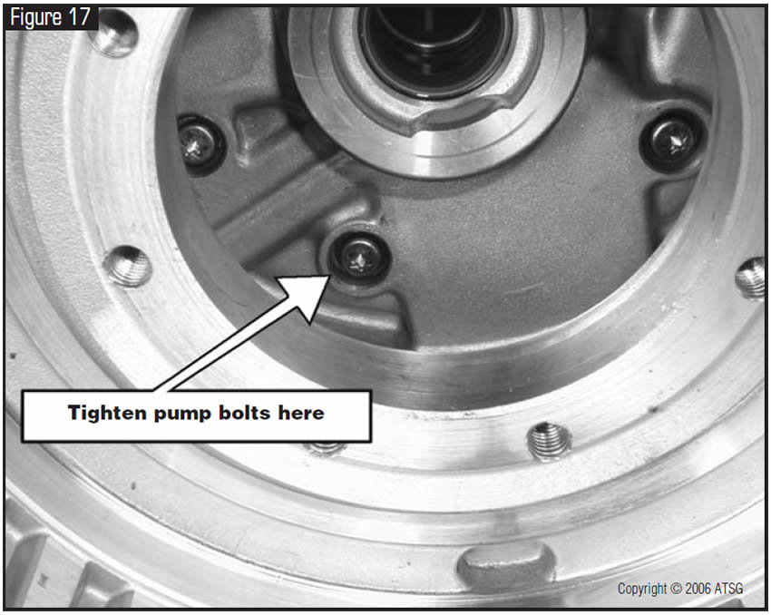
Bolt the front case half onto the rear case. Then, from the back of the rear case, with a 3/8-inch extension, swivel adapter and #30 Torx bit, tighten the pump bolts (see Figure 17). Remove the pump from the case and torque to the specifications listed above. This procedure should be considered only as a last resort if the alignment tool is not available at the time of assembly.

- Low/reverse wave spring . . . . . . . . . . . . . . . . . . .M R 534166

May 2006 Issue
Volume 23, No. 5
- Dodge Trucks & Vans with RE RWD Transmissions: Erratic Governor Pressure
- Chrysler RE RWD Transmissions: Cycling In and Out of Lockup
- 1990-93 Honda Accord: ‘S’ or ‘D4’ light always On and Stuck in High Gear
- Dodge, Chrysler, Hyundai & Mitsubishi: Broken Pump Gears – F4A41/42/51-Series Transaxle