


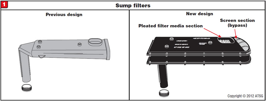
2008-up Ford/International vehicles equipped with the 5R110W now have a redesigned “high-efficiency” sump filter and pan.

Better filtration of the transmission fluid. This helps prevent solenoid mechanical problems and the gear-ratio errors related to them.

Sump filter: Refer to Figure 1 for a view of the previous- and new-style filters.
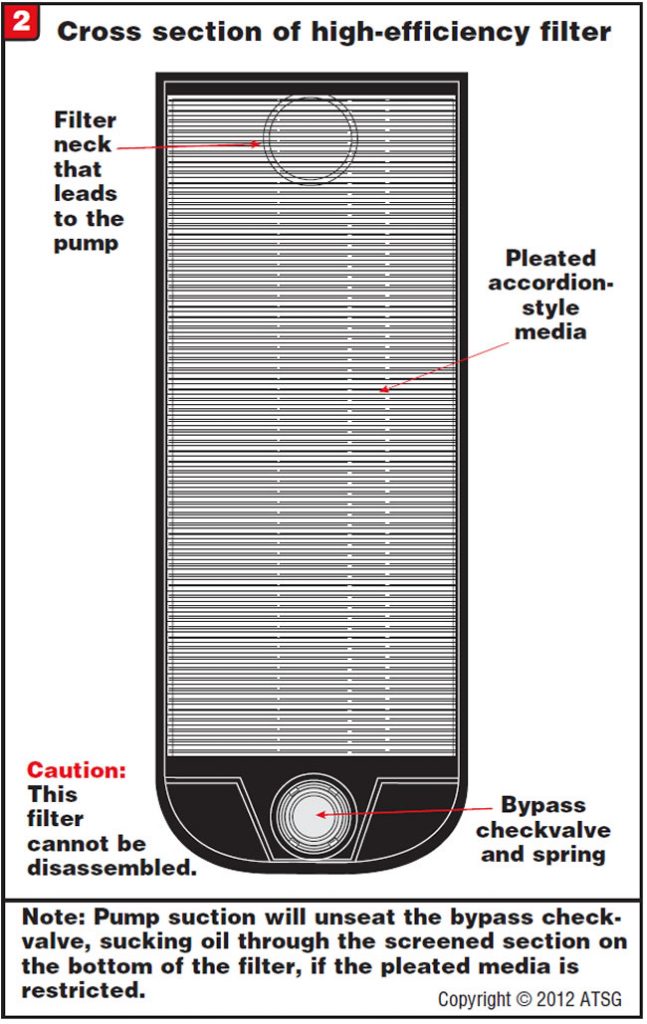
The high-efficiency filter now uses an accordion-style pleated media and also has a built-in bypass in case of restriction. Figure 2 shows a cutaway of this filter.
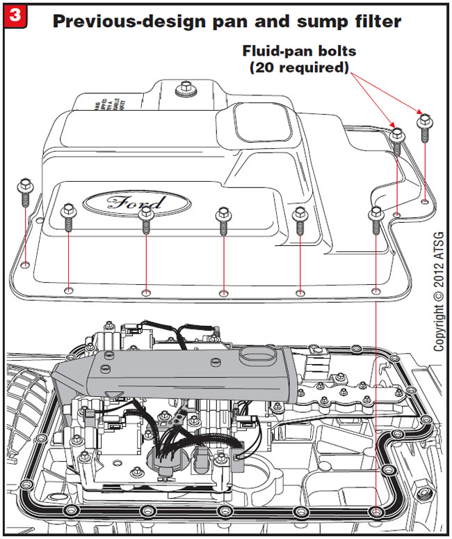
Pan: The pan was redesigned to accommodate the changes in the high-efficiency filter. Figure 3 shows the previous-design filter and pan, and Figure 4 shows the new high-efficiency filter and pan.
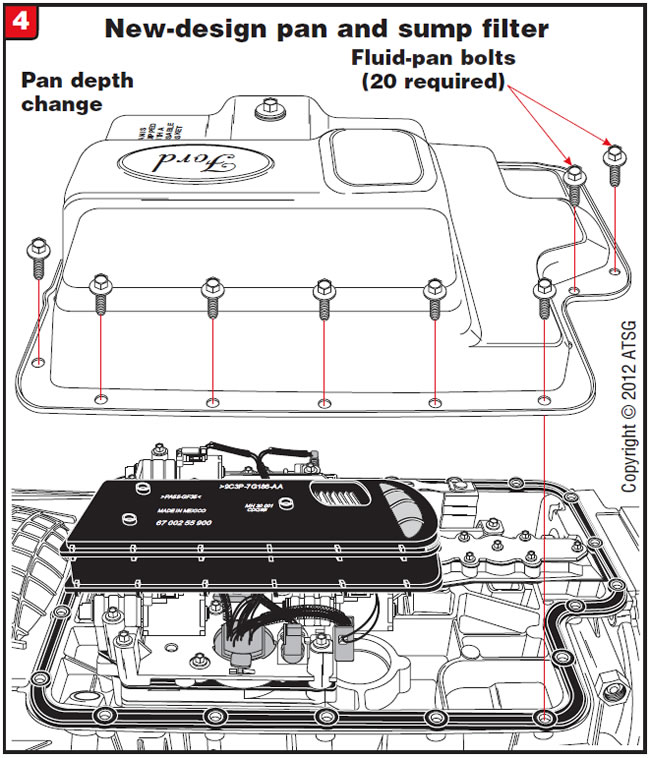

The new-design parts will retrofit to previous versions as a set.

- High-efficiency filter (Ford part #) . . . . . . . .8C3Z-7A098-D
- Pan (Ford part #) . . . . . . . . . . . . . . . . . . . . .8C3Z-7A194-B


Ford 4X4 models equipped with the 5R55W/S transmission may exhibit a complaint of a clank or metallic noise during engagement into any forward or reverse range. This noise is typically perceived as a differential or transfer-case problem.

The cause may be that condensation has built up in the area between the output-shaft splines and the transfer-case input splines, causing the splines on the output shaft to rust and resulting in deterioration of the spline. This causes clearance between these two items, which creates the metallic noise during engagements.

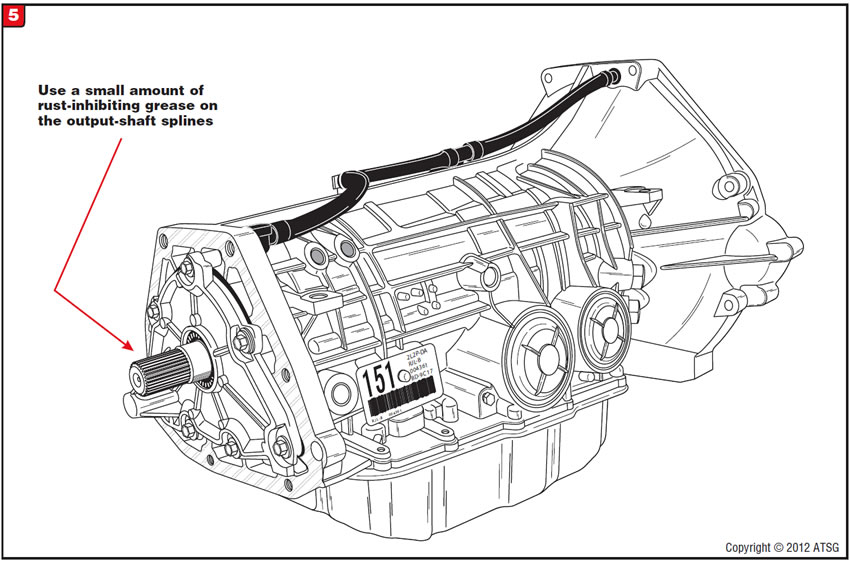
To correct this condition, you will have to remove the transfer case so you can inspect the splined area on the output shaft (Figure 5). If there is rust buildup in this area, the output shaft in the transmission will have to be replaced. After replacement, it is highly recommended to use a small amount of synthetic grease that is a rust inhibitor to coat the splines so this problem does not happen again.
Numerous types of synthetic rust-inhibiting grease products are available. Two common ones are the high-temp urea grease available from your local Honda/Acura dealer and a high-temp brake and caliper grease available from your local auto parts store.

A late-model Ford Crown Victoria (usually a police vehicle) comes into the shop with the transmission slipping. Upon disassembly it is obvious that the transmission was overheated. Once the transmission is installed and the vehicle is road tested, the technician notices that the transmission temperature is rising above a normal operating level. The vehicle is brought back into the shop and cooler flow is checked only to find out that the flow rate is far too great. The flow rate was one gallon in 15 seconds instead of the normal standard of a quart in 20 seconds. At this time the technician realizes that the transmission fluid is bypassing the cooler and not giving off its heat, resulting in a transmission operating temperature of about 270°F.
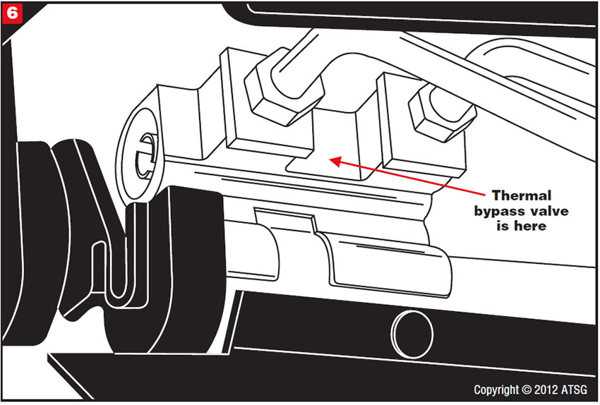
These as well as some other Ford vehicles use a unique transmission cooler that is integrated with the A/C condenser as one unit. At the lower driver-side corner of the ATF cooler where the cooler lines enter (Figure 6) is a thermal bypass valve (Figure 7). These valves are allowing oil to bypass the cooler even though the transmission is fully warmed up, resulting in the complaint mentioned.
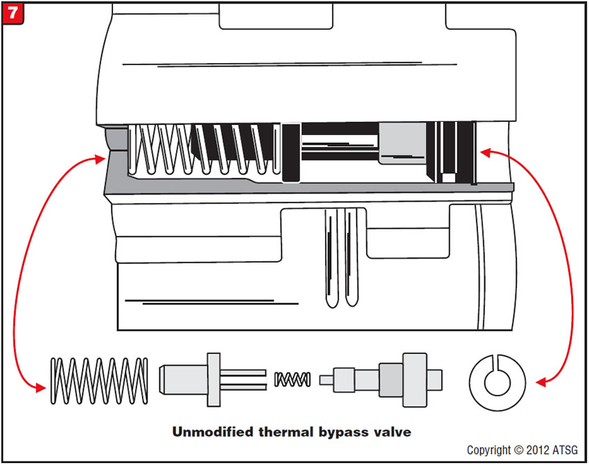
In some instances the municipality will not stand the cost of a replacement ATF cooler/air-conditioning condenser. The thermal bypass valve can be rendered inoperative, allowing fluid to circulate through the cooler at all times.
Note: This may not be a good option in colder climates because of the possibility of fluid jelling.
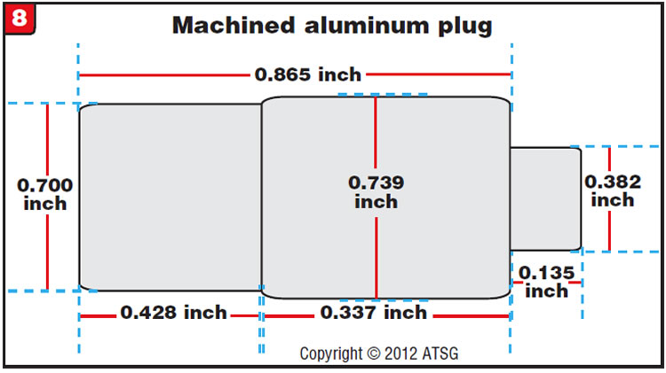
Performing the bypass-valve modification requires machining an aluminum plug (Figure 8). Remove the bypass-valve assembly from the cooler. Using round aluminum stock 0.9 inch in length and at least 0.739 inch in diameter, machine in one end a locating dowel pin 0.382 inch in diameter and about 0.135 inch in length. Next, machine a 0.337-inch length of the aluminum stock to 0.739 inch in diameter. Next, machine a 0.428-inch length of the remaining aluminum stock to a diameter of 0.700 inch.
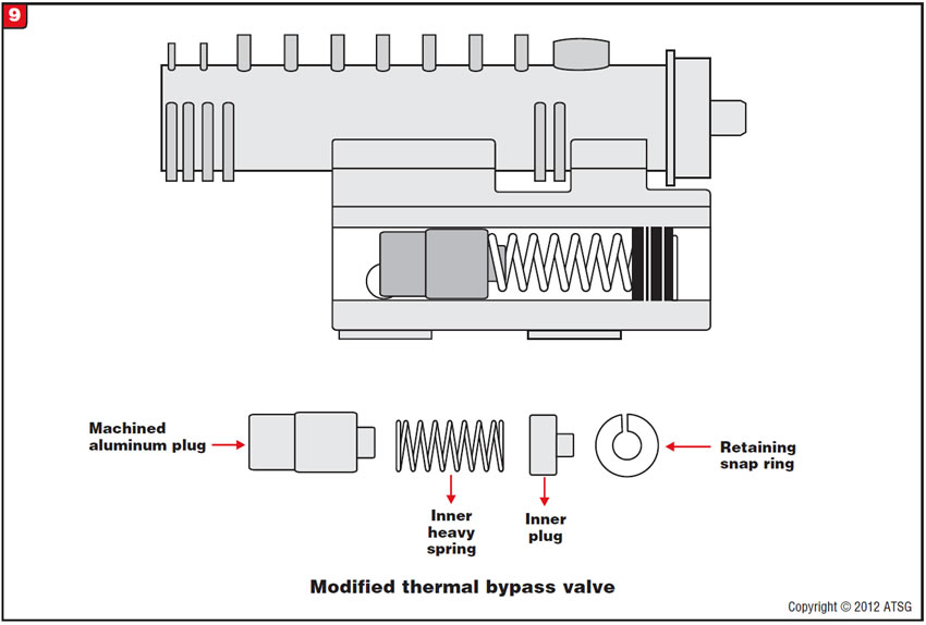
Insert the machined aluminum plug with the 0.700-inch end into the bypass-valve housing, then install the inner heavy spring, followed by the inner plug and retaining snap ring
(Figure 9).
After this modification is completed, transmission operating temperature was 175°regardless of run time and accessory usage.


A 2009 or later Ford vehicle equipped with the 4R75E has a complaint of improper gear selection, erratic converter-clutch operation or improper shift feel. Various diagnostic trouble codes are stored, including P0712, P0740, P0743, P0748, P0750, P0753, P0755, P0758, P0962 and/or P0963. Depending on vehicle model as to which circuits are shorted, those circuit fuses, in the battery junction box, also may be blown. As a result of the blown fuse, the transmission could be stuck in a higher gear, resulting in engine drivability problems.
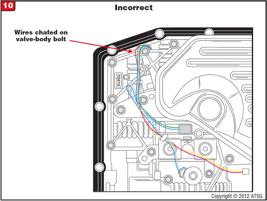
The Ford line of 4R75E-equipped vehicles has returned to soft internal wiring as of the 2009 model year, allowing the internal harness to be routed incorrectly and causing it to chafe on a valve-body bolt (Figure 10).
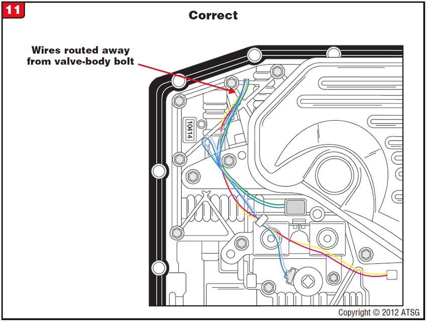
Route the internal wiring as shown in Figure 11.
Note: This problem could occur on vehicles that have left the factory if those vehicles were built before 12/1/2008.
- 2009 & later 4R75E internal wire harness . . . . . . . . . 9L3Z-7G276-A

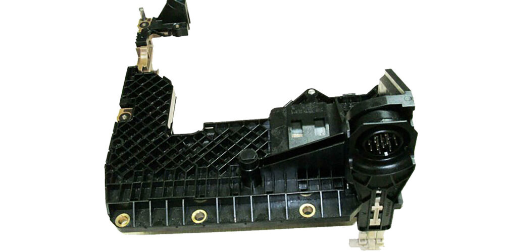
When solenoid-performance codes are stored on vehicles equipped with these transmissions, it is difficult to determine whether a solenoid is mechanically bad. Without definitively knowing whether it is a mechanically malfunctioning solenoid, the shop may buy the entire control unit, which includes the solenoids, for no good reason.
Solenoid-performance codes usually are mechanically generated. These codes can be caused by mechanically defective solenoids, valve problems, a leak in the component hydraulic circuit or a problem with the component itself.
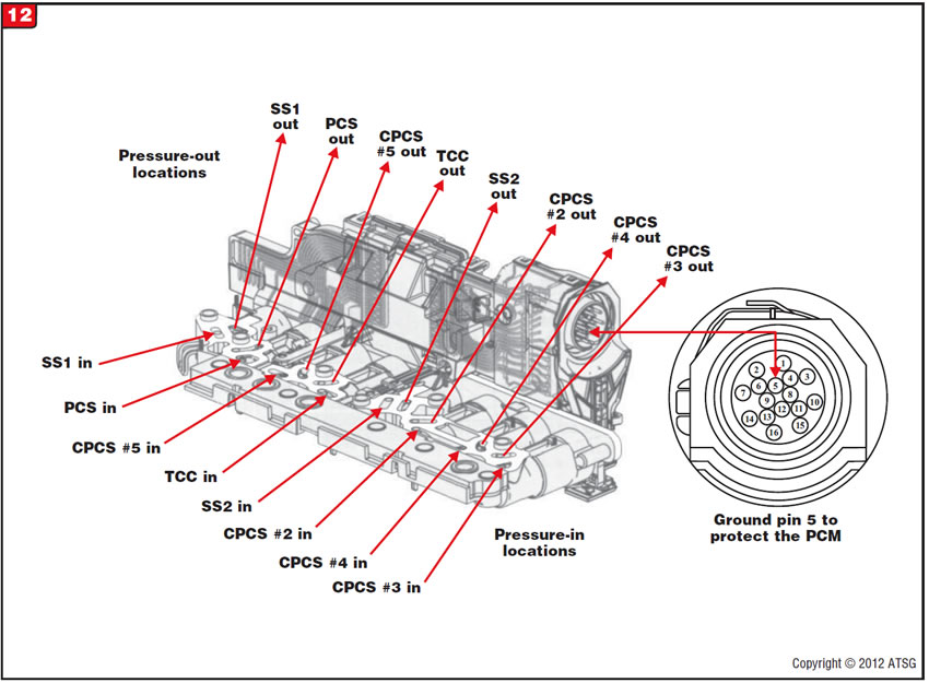
Before solenoid testing begins, ground pin 5 in the control unit to protect the TCM (Figure 12).
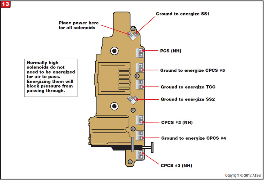
Next, supply power to the control unit shown in Figure 13 and then supply ground to each solenoid one at a time.
At this time you should apply air pressure to the solenoid pressure-in circuit in the control unit (Figure 12) while the solenoid is grounded to energize it, and that air pressure should now exhaust through the solenoid pressure-out circuit in the control unit.
While performing this test remember that some solenoids will exhaust when energized and some will exhaust while not energized.
- Shift solenoids 1 and 2 are normally closed. Pressure-control solenoid is normally high.
- TCC solenoid is normally low.
- Clutch-pressure-control solenoids are normally high.

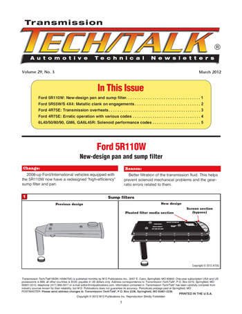
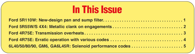
March 2012 Issue
Volume 29, No. 3
- Ford 5R110W: New-design pan and sump filter
- Ford 5R55W/S 4X4: Metallic clank on engagements
- Ford 4R75E: Transmission overheats
- Ford 4R75E: Erratic operation with various codes
- 6L40/50/80/90, GM6, GA6L45R: Solenoid performance codes