

Since the 722.6 transmission shifts from clutch to clutch, proper shift overlap is required for smooth shifting. To accomplish this task, numerous components and strategies combine to allow for adaptation under various driving conditions. Looking at and understanding these components and strategies independently will enable you to appreciate fully what it takes to make for correct shift timing and shift feel.
Hydraulics
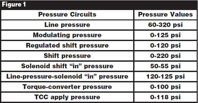
One of the difficulties a transmission technician faces when working with a 722.6 transmission is the absence of pressure taps. Hydraulic pressures are calculated from input signals such as engine torque, engine speed, accelerator-pedal position, cruise-control request, wheel speed, traction status, kick-down switch, selector-lever signal and the program-select switch W/S. If pressure taps were available, there would be essentially eight different pressure categories, as you can see listed in Figure 1 with their respective range specifications. The information was provided by the DaimlerChrysler Academy of Technical Training.
Shift Solenoids
There are three shift solenoids, the 1-2/4-5 (Y3/6y3), 2-3 (Y3/6y5) and 3-4 (Y3/6y4). Just by their names you can determine their functions. Obviously, the 1-2/4-5 solenoid is responsible for the 1-2 and 4-5 upshifts and the 5-4 and 2-1 downshifts. Then, of course, you have the 2-3 solenoid for the 2-3 and 3-2 shifts, and the 3-4 solenoid handles the 3-4 and 4-3 shifts. Each of these three solenoids is fed with 50-55 psi of pressure, called “solenoid shift pressure,” which is controlled by the shift-solenoid “in”-pressure valve.
Pressure Solenoids
There are two pressure-control solenoids. One is called the modulating-pressure-regulating solenoid (Y3/6y1), and the other is the shift-pressure-regulating solenoid (Y3/6y2).
The modulating-PR solenoid regulates pressure between 0 and 125 psi, which influences the pressure-regulator valve to increase main line pressure (working pressure) from a static 60 psi to as high as 320 psi depending upon torque input. This modulating-PR-solenoid oil also influences the 1-2/4-5, 2-3 and 3-4 shift-overlap valves so that the shift overlap of releasing and applying clutches corresponds to torque input.
The shift-pressure solenoid regulates pressure between 0 and 120 psi, which influences the shift-pressure-regulator valve for a controlled clutch-apply pressure (shift pressure) during a shift transition only. This transitional clutch-apply pressure ranges from 0 psi to as high as 220 psi depending upon torque input.
Each of these solenoids is fed with a maximum of 125 psi from the line-pressure-solenoid “in”-pressure valve.
Solenoid Shift Chart
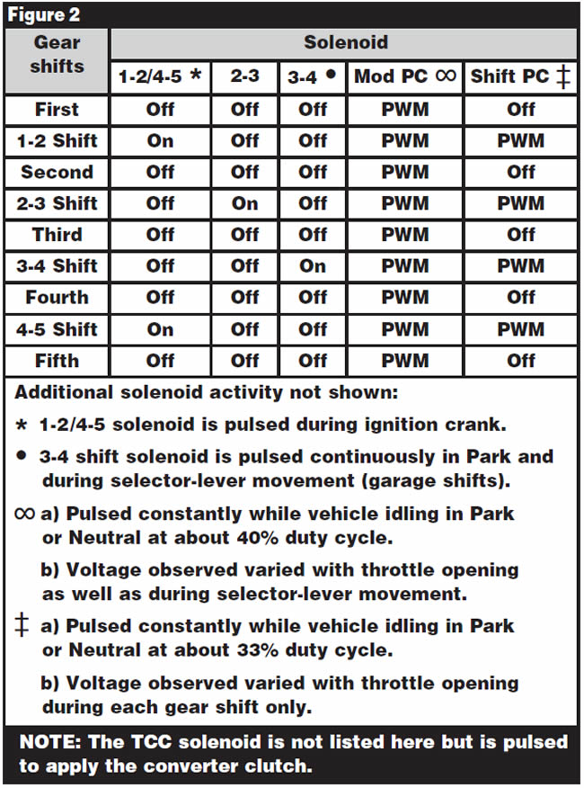
As a reminder for those of you who have read past articles on the unique solenoid shift pattern this unit has, you will notice from the solenoid shift chart in Figure 2 that shift solenoids 1-2/4-5, 2-3 and 3-4 are toggled on-to-off to make their respective shifts. While the transmission is in gear they remain in the off state. This explains how when the vehicle is being driven and the computer system detects a fault, the transmission remains in the current gear when it goes to failsafe mode. After the vehicle is brought to a stop and the ignition is cycled, the transmission will default to second gear.
Shift Groups
By viewing the mechanical, hydraulic and electrical operation of a shift, you can observe that a specific solenoid and a group of valves, described as a “shift group,” cause a clutch-application change. A shift group has two phases. The transition from one gear to the next is called a “shift phase.” Once the shift is complete and the transmission is in gear it is called the “stationary phase.” There are three shift groups to achieve five forward speeds. In a shift phase, a shift solenoid initiates the application of one group of valves to change the clutches required for that shift. During this time the other two groups remain in the stationary phase.
The three shift groups are:
K1/B1 (gear changes 1-2/4-5)
This group, which controls the 1-2/2-1 and 4-5/5-4 upshifts and downshifts, consists of:
- K1 clutch
- B1 brake
- 1-2/4-5 command valve
- 1-2/4-5 holding-pressure shift valve
- 1-2/4-5 shift-pressure shift valve
- 1-2/4-5 overlap valve
- 1-2/4-5 shift solenoid (Y3/6y3)
K2/K3 (gear change 2-3)
This group, which controls the 2-3/3-2 upshift and downshift, consists of:
- K2 clutch
- K3 clutch
- 2-3 command valve
- 2-3 holding-pressure shift valve
- 2-3 shift-pressure shift valve
- 2-3 overlap valve
- 2-3 shift solenoid (Y3/6y5)
K3/B2 (gear change 3-4)
This group, which controls the 3-4/4-3 upshift and downshift, consists of:
- K3 clutch
- B2 brake
- 3-4 command valve
- 3-4 holding-pressure shift valve
- 3-4 shift-pressure shift valve
- 3-4 overlap valve
- 3-4 shift solenoid (Y3/6y4)
Computer Strategy
In the beginning of the article, under the heading “Hydraulics,” we mentioned how internal transmission pressures are controlled and calculated from various inputs to the TCM. The TCM uses these inputs to perform proper shift timing and shift feel under diverse driving conditions through four basic adaptation programs: driving style, shift time, fill pressure and fill time.
Driving-Style Adaptation
The driving-style adaptation is a program ready to adapt to the driving condition as it happens. The TCM continuously monitors vehicle speed and throttle opening as well as the rate of change of the throttle as it opens and closes. It also looks at lateral acceleration, which is a term for curve recognition. Basically, it monitors wheel speeds to determine whether the vehicle is in a turn.
In addition to these inputs it also monitors the frequency of gear changes. As a result, it can quickly adapt to a shift time and feel appropriate for the present condition. This adaptation is not written to memory. It is known as an adaptation that “lives for the moment.”
Shift-Time (Shift-Overlap) Adaptation
This strategy focuses on the quality of the upshifts and down-shifts while under both load and no-load conditions. Shift-time adaptation gives the TCM the ability to electronically alter the time it takes to go from one gear to another; in other words, the time it takes to disengage one clutch while applying another. Once the TCM has calculated the type of shift that needs to take place, it uses the following two strategies to accomplish the task:
Fill-Pressure (Apply-Pressure) Adaptation
This strategy gives the TCM the ability to control and modify the pressure used to engage a clutch, which determines the type of shift feel that will occur.
Fill-Time (Preload-Pressure) Adaptation
This strategy gives the TCM the ability to control the time it takes to fill a clutch drum, bringing the clutch pack to a “0” clearance but not yet applying the clutch. This adaptation compensates for wear of the friction plates.
Scan-Tool Diagnosis
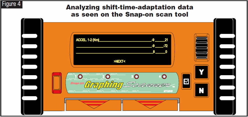
Shift-Time Adaptation (see figures 3 & 4)
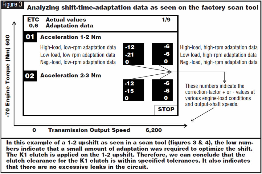
Specific values are needed to make the shift-time adaptation, and these values are written to memory, enabling the ETC to adapt during the following shift occurrences:
- Accelerating upshifts: Upshifts that occur under load
- Deceleration upshifts: Upshifts that occur under no load
- Accelerating downshifts: Downshifts that occur under load
- Deceleration downshifts: Downshifts that occur under no load (coast-down shifts)
These values are represented in Newton meters (Nm), meaning torque; in other words, the strength of the shift. There are no ideal numbers to achieve. For example, if a 1-2 upshift that occurs under load with an eight-cylinder engine has a 190-Nm reading and the shift quality is acceptable, one may consider that the computer is able to handle and overcome the existing clutch clearance or a slight leak in the system without a flare on the shift and possible premature damage to the applying clutch. A 0 reading indicates that a clutch pack either does not require adaptation or has not yet adapted. However, if an adaptation reading is at its maximum value and the shift is unacceptable, repair work may be required. Additional adaptation cannot be achieved when the following values are reached:
Maximum values in Nm:
8- and 12-cylinder engines + or – 210 Nm 6-cylinder engines + or – 180 Nm
4-cylinder engines + or – 150 Nm
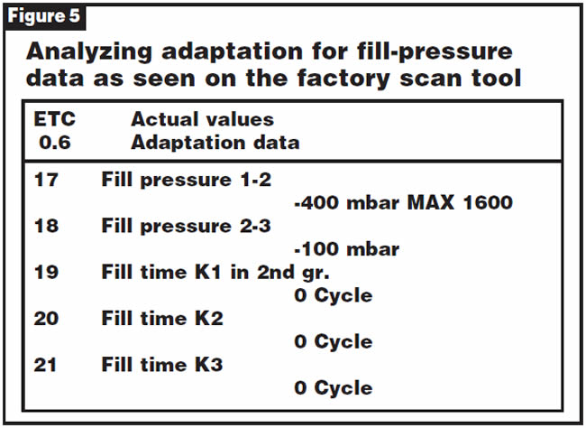
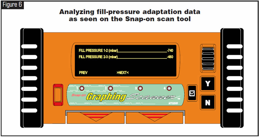
Fill Pressure
Fill pressure (see figures 5 and 6) is measured and presented in millibars (mbar). Higher values indicate that the TCM is increasing fill pressure to produce a firmer shift. Lower values indicate that the TCM is decreasing fill pressure to produce a softer shift. A reading of 0 mbar means that either the TCM has not stored an adaptive value or the shift member does not require correction. A value at the parameter’s upper limit, along with poor shift quality, indicates the need for repair.
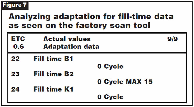
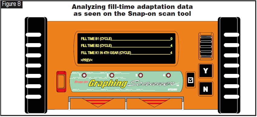
Fill Time
Data parameters for fill time (see figures 7 and 8) are displayed in cycles of time. The TCM controls the two pressure solenoids with an amplitude-modulated current. Amplitude means the highest value of a periodically varying quantity. The greater the signal amplitude, or difference between the highs and lows of the signal, the greater the pressure. The TCM can change signal ampli-tude only once every 20 milliseconds (ms). Each cycle displayed by these data parameters equals one 20-ms period. If the scan tool reports a fill-time adaptation of three cycles, this means that it took three periods of 20 ms each (60 ms) to alter pressure enough to accomplish the correct application of the shift member. The maximum fill-correction time is 15 cycles, or 300 ms. A value of 0 cycles indicates no fill correction was needed.
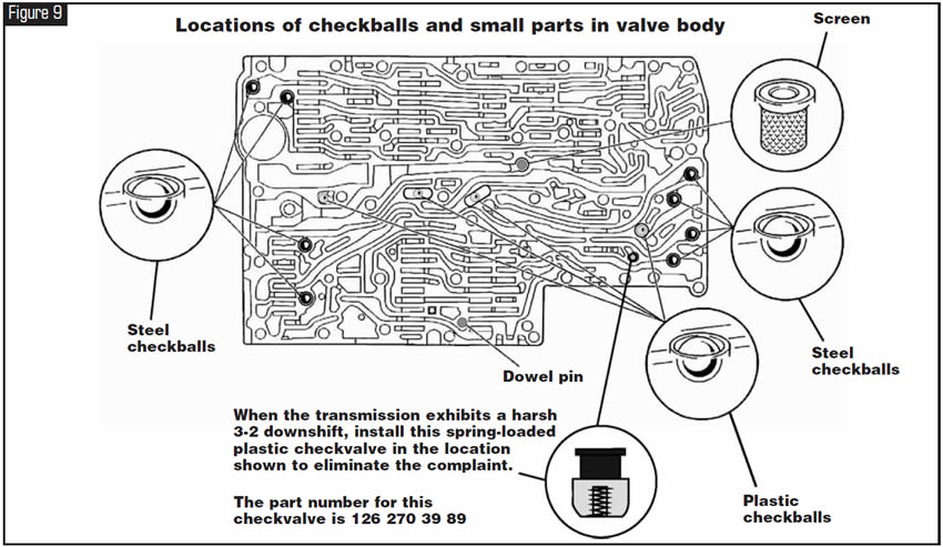
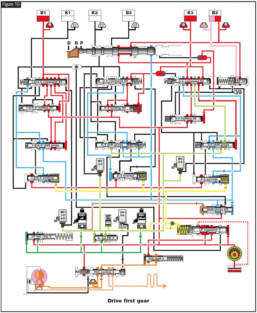
Exhaust Circuits
A shift-overlap valve in the valve body controls the decrease in pressure of a releasing clutch. In addition, there are checkballs that assist in metering the vented pressure (see Figures 9 and 10).


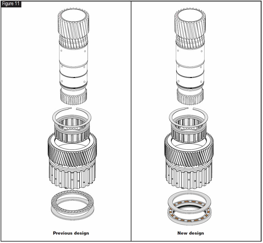
After a rebuild using a new K3 clutch hub, insufficient clearance occurs, preventing the installation of the rear snap ring that holds the entire clutch assembly in place on the output shaft.

The new-design K3 clutch hub and rear sun gear have a flat spacer and ball bearing pressed into the hub assembly, replacing the previous-design open-face needle-bearing and washer design (see Figure 11).
In many instances, a brand-new K3 clutch hub did not have the bearing fully pressed into the hub against the flat spacer. This prevents the hub from being positioned correctly, causing the insufficient clearance for the final retaining snap ring (see Figure 12).
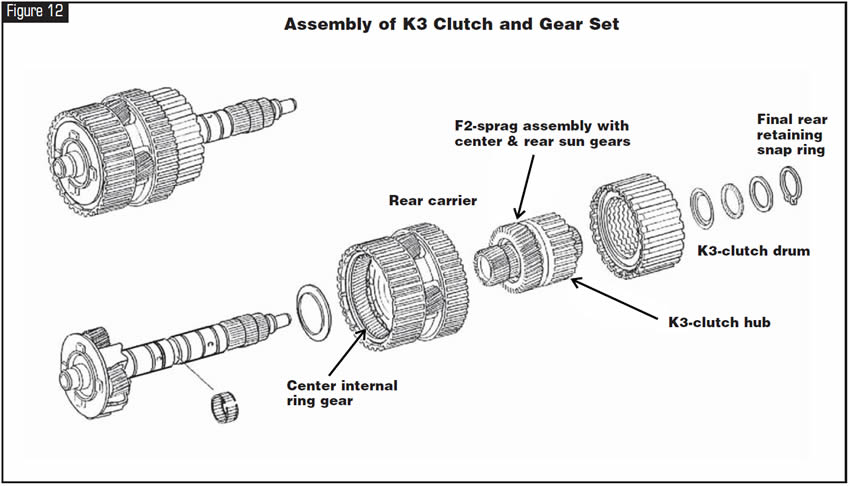

Fully seat the bearing into the K3 hub assembly.


June 2006 Issue
Volume 23, No. 6
- Shift Groups: Principles of Operation
- Assembly Difficulties: K3 Hub and Rear Sun Gear


