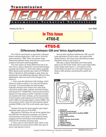


The 4T65-E transmission is used both in General Motors vehicles beginning in 1997 and in Volvo 80 series starting in 1999. There are several major differences between these units that can cause some problems with parts interchangeability.
The main reason for these differences has to do with Volvo’s using a Geartronic manual-shift-strategy package (see Figure 1). Volvo also makes available GM’s typical seven-position gear select of PRND321. When a Geartronic shift package is used, there are significantly more differences between GM and Volvo applications. Here are most of the changes to be aware of:

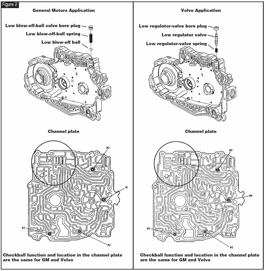
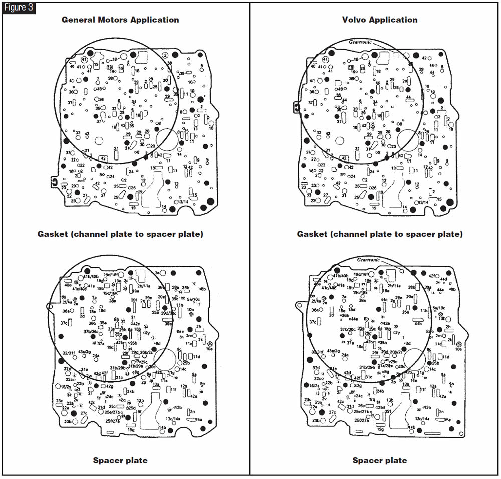
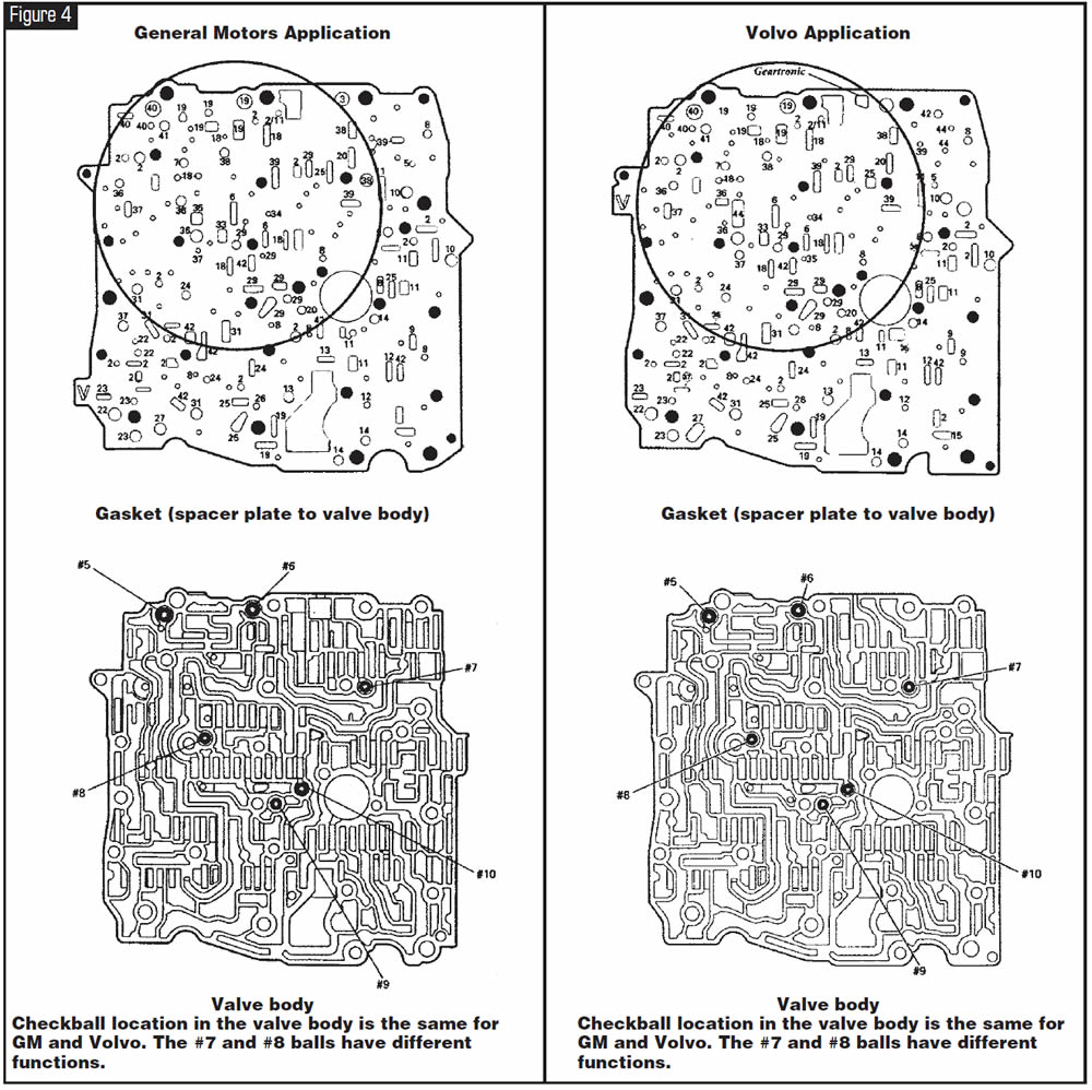
Change 1: Volvo uses the Geartronic shift strategy, which allows for engine braking in 1st, 2nd and 3rd gears manually. To accommodate this shift strategy, hydraulic changes were made to the valve body, valve-body spacer plate, gaskets and channel plate (see figures 2-4).
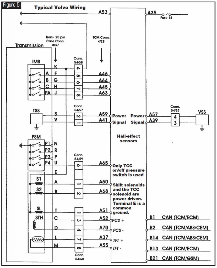
Additionally, manual-valve-position signals from the pressure-switch manifold no longer are needed with Volvo vehicles, as the transmission control module reads signals from the internal mode switch (IMS) and the gear-select module (GSM). The only pressure switch used from the pressure-switch manifold (PSM) is the TCC on/off switch (see Figure 5).
Vehicles that use the seven-position gear-select assembly make full use of the PSM.
Although the TCM does not use all the signals from the PSM with the Geartronic package, the internal wiring harness is the same. It is the external wiring plugging into the transmission that eliminates the wiring for the switches not being used.
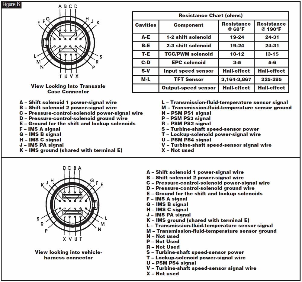
Change 2: Volvo uses an Aisin Warner-style TCM, so the shift solenoids are power driven rather than ground driven (see figures 5 and 6).
Among other significant differences, GM uses AC pulse generators for the turbine- and output-shaft speed sensors, and Volvo uses internally grounded Hall-effect sensors (see Figure 5).
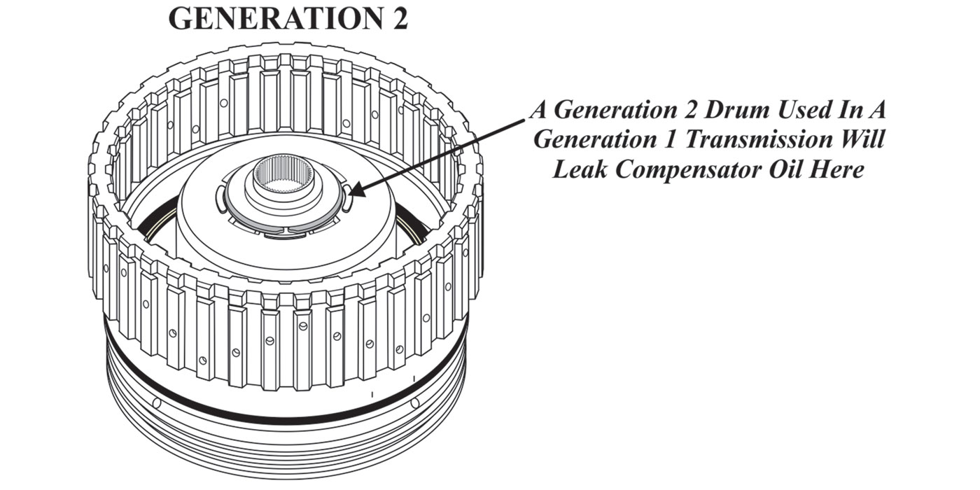
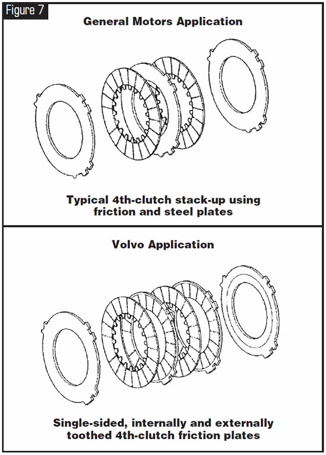
GM uses a typical steel-plate and friction-plate stack-up for the fourth clutch; Volvo uses single-sided friction plates (see Figure 7). The splines on the fourth-clutch hub strip out in the same manner as those in GM vehicles, preventing the upshift into fourth.
Shifting in Geartronic mode
When the gear selector is moved to the Geartronic position (MAN), the automatic transmission remains in hydraulic position D, but when the gear selector is moved upward (+), the gear-selector module (GSM) transmits a signal to the TCM to upshift. When the gear selector is moved downward (-), the GSM signals the TCM to downshift. The driver information module (DIM) switches the symbol in the combined instrument panel from D to the current gear; for example, 3 when the gear selector is in the MAN position. A signal is sent to the GSM to light the M LED and switch off the other LEDs. The TCM determines whether shifting can be carried out, and the DIM indicates the current gear. If shifting is permitted, the solenoids are activated according to each specific gear pattern. However, in certain situations the TCM assumes the shifting decision.
The following applies:
- When the vehicle is stationary, only first, second and third gears can be selected. Fourth gear can be selected at speeds exceeding 30 km/h.
- Automatic downshifting takes place for all gears below a certain speed. Example: 2nd gear is selected.
- Automatic downshifting occurs when shifting from 2nd gear to 1st at 2 km/h if the speed before this has exceeded 25 km/h. In other instances 2nd gear is retained; for example, when 3rd gear is engaged despite the car’s being stationary.
- Manual upshifting is required after automatic downshifting. Kick-down is not available in the Geartronic position (MAN).
- The permitted speed for manual downshifting corresponds to those for kick-down shifting; i.e., engine speed about 6,000 rpm.
- If the transmission temperature becomes too high, the TCM determines the shift position. The purpose is to maintain a gear in which lockup is possible at the current speed.
- Lockup is possible in 3rd and 4th gears (1st and 2nd gears do not have lockup).
Other
In the MAN position a signal indicating the lever position is generated for the GSM as follows:
For each of the three gear-selector positions, a Hall-effect sensor is mounted on the printed circuit board for the GSM.
A permanent magnet on the lever affects the output signals from the sensors to the control module.
The control module can read off the position of the lever through the differences in the signal characteristics.
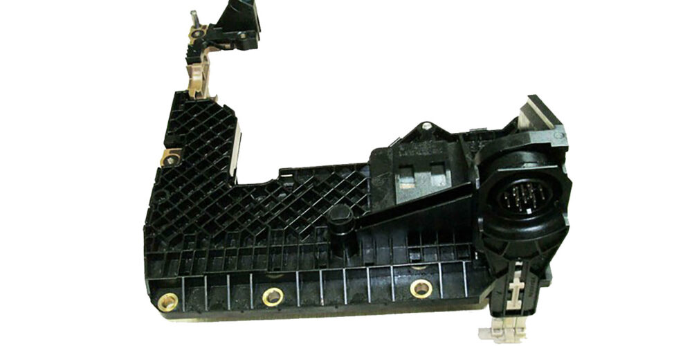
Construction of gear-selector assembly
The housing, shift-lock solenoid (item 1 in Figure 1) and mounting lever for the ignition-switch interlock cable are common to both gear-selector assemblies.
In the 4T65-EV/EV-GT the solenoid in the gear-selector assembly has a reverse-inhibitor function. The reverse inhibitor makes it impossible to engage R and P when the car is traveling faster than 12 km/h. The gear-selector assembly (and, therefore, the solenoid) is supplied with current and signals via the connector on the rear side.
A printed circuit board (2) is under the top panel (3). The circuit board has the WINTER button (8) and 14 LEDs (13 LEDs with Geartronic) that light up to indicate the gear position (4). The LEDs also indicate the selected gear.
Gear-selector module
The gear-selector assembly, solenoid and printed circuit board together constitute the gear-selector module, which is a slave module to the TCM.
Information is transferred between the gear-selector module and the transmission module using serial communication, which requires a microprocessor on the printed circuit board.
The TCM gives instructions to the GSM about which LEDs should be illuminated and to what strength of illumination. In addition, the TCM controls the solenoid connection at the reverse inhibitor.
The gear-selector module informs the TCM about the position of the WINTER button and controls the connection of the solenoid for the reverse-inhibitor function. In Geartronic, information is sent about the gear-shift position in MAN and if the gear-selector lever is moved backward or forward.
The gear selector module is connected to the transmission diagnostic system.
The transmission is electronically controlled by the TCM, which controls it on the basis of signals from the network and sensor in the transmission.
The TCM has built-in diagnostics, read via the data-link connector using VADIS.
Shifting Program
Economy mode
When the vehicle is being driven at normal acceleration, the TCM uses a preset shifting program, optimized to shift for fuel economy. This shifting program is suitable for “normal” driving, providing earlier upshifts and lockup. In addition the transmission oil pressure is adjusted to provide smooth gear engagement.
Sport mode
In sport mode, the shift points are adjusted to optimize performance. Downshifts occur earlier. The TCM selects the shifting and lockup points that provide the best possible performance. The transmission switches from economy mode to sport mode in step 1 or step 2 if the accelerator pedal is pressed down quickly. The conditions are that the throttle opens and the vehicle speed exceeds 50 km/h. As soon as the accelerator pedal is released to a certain level, economy mode resumes.
Kick-down program
At wide-open throttle (WOT) the kick-down function is engaged, providing quick downshifts for maximum performance. In this way the driver can obtain a burst of power for overtaking another vehicle, for example.
Winter mode
The driver selects the winter mode with the W button on the top panel of the gear-selector assembly. Winter mode enables starting off in a high gear to prevent the wheels from spinning on a slippery surface. This mode also can be used in other difficult situations in which the driver needs more-direct control over gear selection. Lockup can be engaged in 1st and 2nd gears. The shifting pattern is optimized to minimize the number of shifts. Depending on the gear position, the following combinations can be obtained:
- D – The car starts in 2nd gear. Automatic shifting between 2nd and 3rd gears occurs earlier than in Economy mode, D position.
- 3 – The car starts in 2nd gear. 4th gear is locked out.
- 2 – The car starts in 2nd gear. There is no upshifting or downshifting.
- 1 – The car starts in 1st gear. There is no upshifting or downshifting.
- The W lamp on the dashboard lights when the driver selects winter mode.
- If kick-down is activated in winter mode, the transmission uses all gears for maximum performance.
Emergency programs in the event of a fault
If the TCM detects a transmission fault (permanent fault), it activates an emergency program to deal with the fault. The control system then implements corrective action to protect the transmission while leaving the car in the best possible drivable condition. Minor malfunctions do not activate an emergency program. There are different programs depending on the type of fault:
- Emergency mode I
- Emergency mode II
- Emergency mode III
- Limp-home mode
Emergency mode I is activated in the event of minor faults, and the Limp-home mode is activated for the most-serious faults. If the malfunction is intermittent, the TCM returns to normal operation the next time the ignition is switched on.
Emergency mode I
- The warning lamp in the combined instrument panel lights (S80), flashes (S/V/C70) for certain diagnostic trouble codes (DTCs).
- The transmission shifts in all gears but
transmits no signal to the lockup solenoid. This means that lockup is not available.
Emergency mode II
- Remedy as for Emergency mode I.
- No reduction of line pressure when the driver moves the gear selector between positions P-R, N- R and N-D. This results in harsh shifting.
- No torque-limiting request from the engine control module (ECM) during gear shifting.
- The warning lamp in the combined instrument panel lights/flashes.
Emergency mode III
- Remedy as for Emergency modes I and II.
- No control of line-pressure solenoid SLT.
Constant maximum system pressure. This results in harsh shifting and harsher gear engagement in positions P-R, N-R and N-D.
Limp-home mode
- The TCM interrupts the activation of all solenoids so that there is no shifting. The transmission operates only in 3rd gear in positions 3 and L, 4th gear in position D and reverse in position R. Shifting can be carried out only manually between 3rd and 4th gears and reverse gear.
- No control of line-pressure solenoid STH. Constant maximum system pressure. This results in harsh shifting and harsher gear engagement in positions P-R, N-R and N-D.
- The warning lamp in the combined instrument panel flashes.
Note! When starting off and driving, the driver should first move the gear selector to position L to minimize stress on the transmission.
Additional information concerning emergency and failsafe modes
If the TCM detects a permanent fault, it activates an emergency mode. The TCM then implements corrective action to protect the transmission, while leaving the car in the best possible drivable condition. Minor malfunctions do not activate an emergency program. There are different programs depending on the type of fault:
- Emergency mode
- Limp-home mode.
Emergency mode is activated for minor faults and the limp-home mode for the most-serious faults. If the malfunction is intermittent, the TCM returns to normal operation the next time the ignition is switched on.
Emergency mode
A text message is displayed in the combined instrument panel for diagnostic trouble codes (DTCs) stored in the TCM. The transmission shifts in all gears but transmits no signal to the lockup solenoid. This means that lockup is not available.
Limp-home mode
A text message is displayed in the combined instrument panel for DTCs stored in the TCM. The TCM interrupts the activation of all solenoids. This means that no shifting is possible. The transmission functions in only 3rd gear and backup (reverse) gear. There is no regulation of line-pressure solenoid STH, and there is maximum system pressure constantly, which results in harsh meshing and harsher shifts during engagement from P-R, N-R and N-D. This also can result in a whining noise from the transmission pump.
Additional Information
Gear ratios:
- 1st 2.921:1
- 2nd 1.568:1
- 3rd 1.000:1
- 4th 0.706:1
- Reverse: 2.385:1
Weight including fluid: 97.0 kg (214 lbs)
Approximate oil capacity: 7.0 liters (7.4 U.S. quarts)
- If the oil pan and the cooling circuit are removed: 7.5 liters (8 U.S. quarts)
- If the oil pan and the torque converter are removed: 9.5L (10 U.S. quarts)
- Completely dry with cooling circuit (theoretical value):12.4 liters (13 U.S. quarts)
- Transmission fluid: Dexron III with G-license number (G-32xxx).
Counter for transmission-fluid data
A counter for transmission oil quality is built into the software for the TCM. The counter tracks the amount of time the oil is above a certain temperature. When the counter has reached the maximum value, the DTC for an oil change is stored in the control module. When you replace transmission fluid, you must reset the counter to prevent a DTC from being stored incorrectly. This applies anytime the transmission fluid is replaced either at scheduled intervals or during a repair.
The reset function is activated via the VIDA vehicle communication socket.
These are some of the more-significant differences that can be found between GM and Volvo applications. Different-size passenger-side axle seals are another, and Volvo also uses a viscous clutch in the differential in some applications.


June 2005 Issue
Volume 22, No. 6
- 4T65-E: Differences Between GM and Volvo Applications